This is one of those antenna projects that started with: “I wonder if…” Designed with my Elecraft KH1 in mind, it covers the 20M, 17M, and 15M with the use of an tuner—similar to how the KH1’s whip antenna operates. It wasn’t something I had a burning need for, but it turned out to be pretty effective.
Concept
For many of my recent activations, I’ve been using my Elecraft KH1 with my base-loaded 12-foot whip. While I built the loading coil for 40M through 17M, I found that the KH1’s internal tuner easily matched the 12-foot whip on 17M and 15M, with the coil bypassed. A 12-foot radiator is resonant somewhere around 19.5 MHz, so it falls in between the 17M and 15M bands. Even though the 12-foot whip is a compromise, I was regularly making DX contacts on those two bands running five watts or less.
That got me thinking about building a more portable antenna for 20M through 15M using a 12-foot radiator. What I came up with was a simple 12-foot wire antenna that uses a loading coil for 20M and just the 12-foot wire for 17M and 15M.
When I thought about it, what I was building was conceptually similar to the Elecraft AX1 antenna and the KH1’s whip antenna. These antennas are close to resonance on 20M and resonant somewhere in between 17M and 15M. My antenna would operate the same way, except it would be almost 8 feet longer. I’ve always had good luck with the AX1 and the KH1’s whip antenna, so I figured my proposed antenna should work even better.
Along with the electrical properties, I wanted to make the antenna small and lightweight, using a #26 AWG radiator along with two 13-foot counterpoise wires. Also, I wanted to use—as much as possible—parts I already had in my junk box.
Parts List
I selected most of the parts based on availability in my junk box. They might not be the optimal choices, but here’s what I used:
- T106-2 iron powder toroid
- #22 AWG enameled wire (approx. 35 inches)
- SPST slide switch. I actually adapted a DPDT slide switch, since I already had a bag of them.
- #26 AWG wire (12 ft for radiator)
- #26 AWG wire (2x13ft for counterpoise wires)
- 2mm banana plugs & jacks (2 sets for connecting the counterpoise wires)
- (2) ring terminals
- BNC female jack
- (2) 4-40 x ¾-inch bolts plus some washers and nuts for the antenna and counterpoise connections. I used a couple of knurled nuts I had on hand.
- Plastic box. I had one that measures about 2.5 x 1.75 x 1 inches.
Construction:
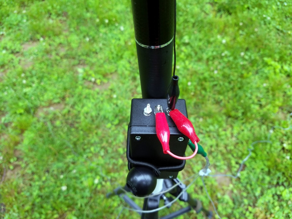
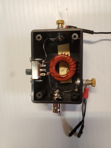
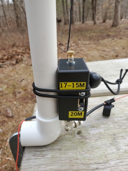
When I first thought about building this thing, I originally envisioned a more field-friendly form factor with built-in winders for the antenna and counterpoise wires. Since I constrained myself to using parts I already had (and I don’t own a 3-D printer), I used a plastic box I bought years ago but never used.
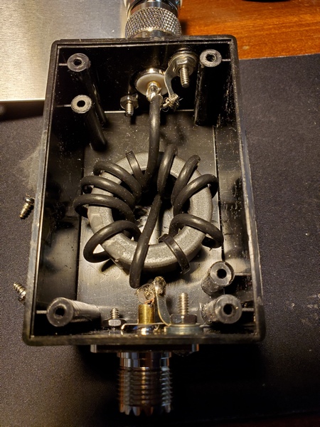
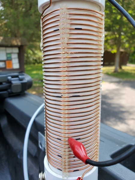
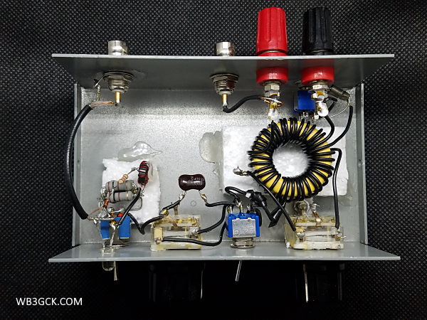
The construction was pretty simple; it’s just a toroid, a switch, and some connectors in a box. They say a picture is worth a thousand words, so have a look at the accompanying pictures to see how I built it.
I used some online calculators to determine the loading inductance needed for 20M. Assuming I would need to tweak the number of turns, I started with one turn more than I had estimated. It’s easier to remove turns than to add turns—don’t ask me how I know this.
I used some foam mounting tape to hold the toroid in place. For good measure, I also wedged in a piece of Styrofoam between the toroid and the lid. That adds some assurance that the toroid won’t come loose in the field. The trickiest part was cutting a square opening for the slide switch. That took some careful work with a nibbler tool and a file to get it done without destroying the box.
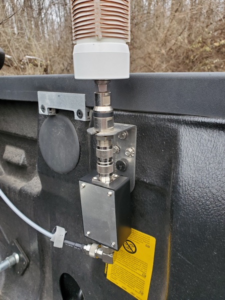
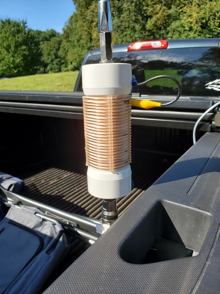
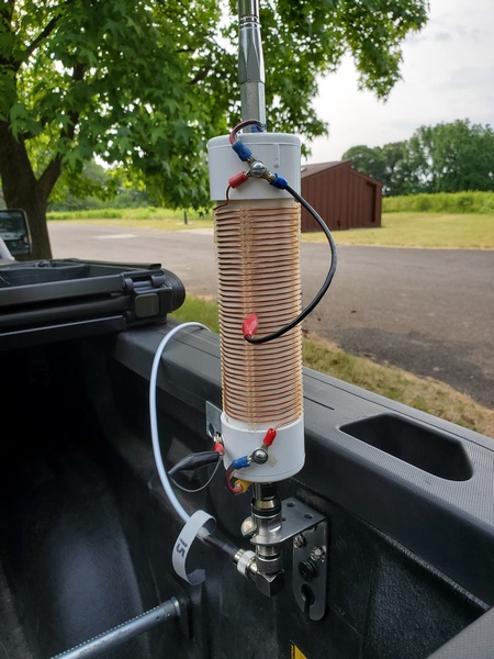
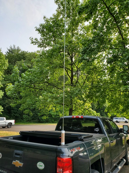
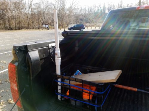
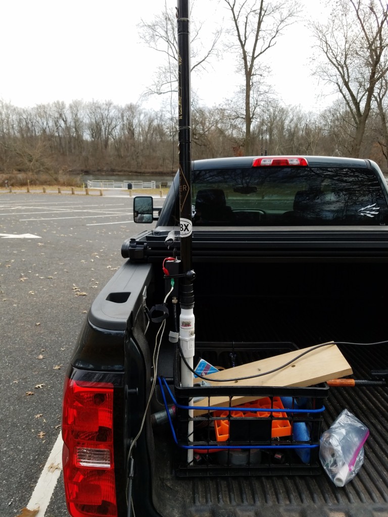
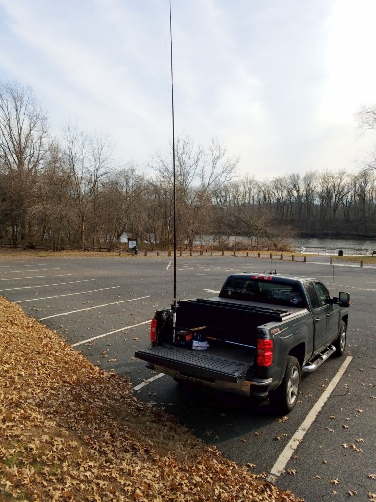
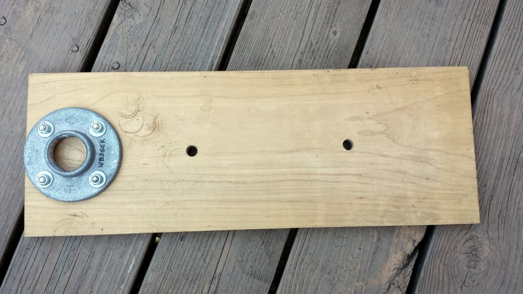
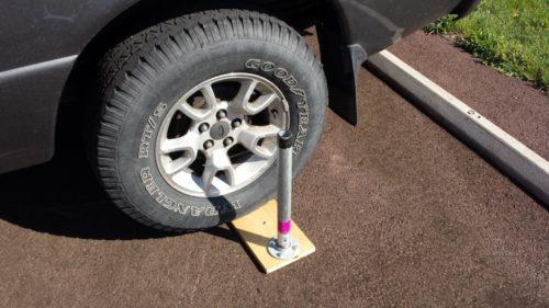
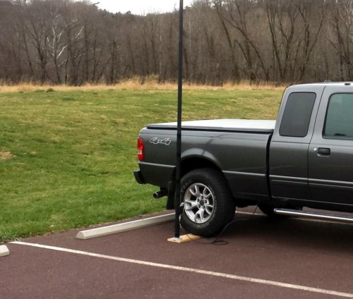
You could use a tree branch to support this antenna, but I like to keep my field setups self-contained. I found a cheap telescopic pole on eBay that measures about 12’ 3” fully extended, so I went with that.
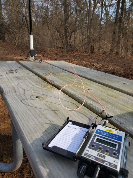
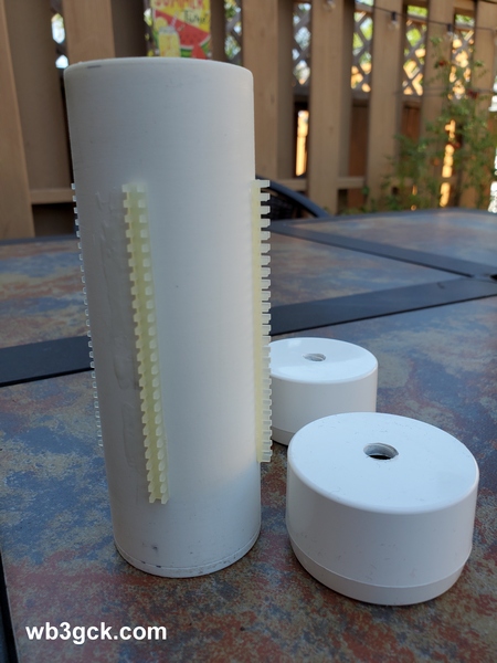
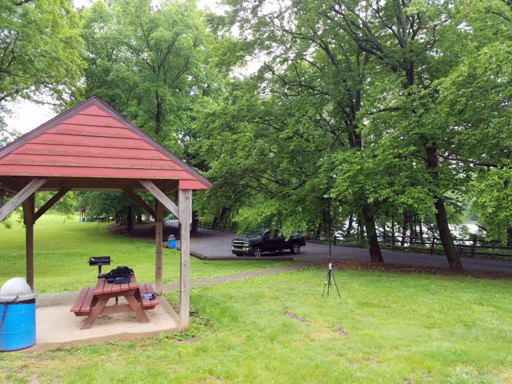
I envisioned using this antenna primarily for “picnic table-portable” operation, running a short length of coax to the radio. Using a piece of PVC pipe and a PVC elbow fitting, I built a simple mount for clamping to a table. As luck would have it, the base of the pole fits perfectly inside a ¾-inch PVC pipe. I just use a C-clamp to fasten the elbow to the table and slide the pole into the pipe. When I built the mount, I inserted a small screw partway up the pipe to give the pole a few more inches of height. A six-foot length of RG316 is more than enough to reach the radio at the other end of the table.
Testing in the Field
I don’t have a good place for antenna experimentation where I live, so it took several trips to the field to tweak the inductor. On each trip, I took readings with an antenna analyzer, made any necessary adjustments to the loading coil when I got back home, and repeated the process on the next outing. That was a tedious process, which was spread out over a few months because of winter weather.
Once I set the antenna up in the field, I found I needed far fewer turns than I originally estimated. Initially, the antenna was resonating well below the 20M band, so I removed a turn at a time. Since I was going to need to use an ATU for 17M and 15M anyway, I didn’t get too fussy about getting it exactly resonant on 20M. However, I eventually got it resonating in the 20M band, with an SWR under 1.5:1 across the band.
The good news was that, even though I hadn’t finished tweaking the coil, the KH1 easily found a match. I had five successful activations during those testing sessions, typically running 3.5 to 4 watts. I consistently worked stations in Europe on all three bands, along with some U.S. stations on the west coast. On one outing, I worked W6LEN in California on all three bands from a park here in southeastern Pennsylvania. During my final testing session with the antenna, I had a 20-minute two-way QRP QSO with DL4ISX on 15M (CW). I declared the project completed at that point.
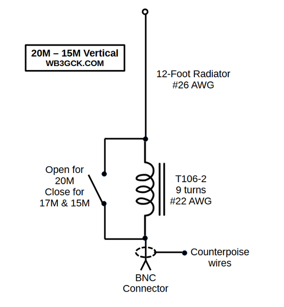
Below is a schematic showing the final configuration:
Wrap-up
So, there you have it. No revolutionary technical breakthrough here, just a fun little project that has been even more fun to use. I envision many more picnic-table-portable activations with it.
72, Craig WB3GCK