[This is an updated version of an article that originally appeared on my QSL.NET website. Although it’s twenty years old, I still occasionally hear from people who have built similar tuners.]
Antenna tuners (more accurately referred to as “transmatches”) make great homebrew projects; they are reasonably simple to build and, when finished, provide a useful piece of equipment. Every shack should have (at least) one. I built this one a couple of decades ago, and it’s still in use.

For this project, I decided to try my hand at building a Z-Match tuner from scratch. This type of tuner has been around for a while. While the Z-match can take on several variations, what distinguishes it from other circuits is that it is a resonant circuit that uses a fixed inductor.

Z-Match tuners became very popular within the QRP community years back, thanks primarily to articles in QRP journals by Charlie Lofgren W6JJZ and the emergence of Z-Match tuners in kit form. Emtech sold its wildly popular ZM-2 kit commercially and the NorCal QRP Club began selling their BLT tuner kit (a W6JJZ design) like hotcakes.
Some Pros and Cons
Why the popularity? Here are some advantages that the Z-match design offers:
- Matches balanced loads without the use of lossy baluns.
- Being a parallel resonant circuit, the Z-match can provide some band-pass filtering for your receiver and harmonic attenuation for your transmitter.
- A well-designed Z-match tuner has a high Q and is more efficient (less lossy) than other types of tuners.
- The fixed inductor simplifies construction (no taps or rollers needed).
- Using a toroid inductor and some small poly-film variable capacitors, the Z-match can be built into a very compact package. This sort of thing usually appeals to QRPers.
There is, of course, no free lunch here. Here are some disadvantages of the Z-match design:
- Tuning is usually very narrow and can be a bit touchy sometimes
- The range of impedances that can be matched is not as great as in other designs, such as the “T” configuration.
Design and Construction
I make no claims of originality for anything in my version of the Z-match. I based it on a classic design which was first appeared in SPRAT #84 (see the G3YCC web site for a schematic of the original design). This design, by the way, is similar to the one used in the Emtech ZM-2.
I incorporated a few modifications in my version, based on an article by W6JJZ (“The Z-Match: An Update”, QRP Quarterly, July 1995, pp 10-11). First, instead of the T-200-2 toroid specified in the SPRAT article, I used a T-200-6 core. W6JJZ recommends the Type-6 core over the Type-2 because it provides a higher Q over most of the HF range. The number of turns has to be adjusted for the Type-6 core, due to differences in permeability. Here again, I went with W6JJZ’s suggested turns count. Another reason for choosing the T-200-6 core was that I happened to have one in my junk box. How convenient!
The coil was wound using some #22 solid hookup wire (from Radio Shack) which I had laying around. The secondary winding is wound between the turns of the primary to ensure tight coupling. I added a toggle switch to ground one side of the secondary winding to accommodate single-ended loads (like a random wire). A piece of styrofoam was glued to the bottom of the enclosure to provide some support for the toroid and to keep it away from metal surfaces.
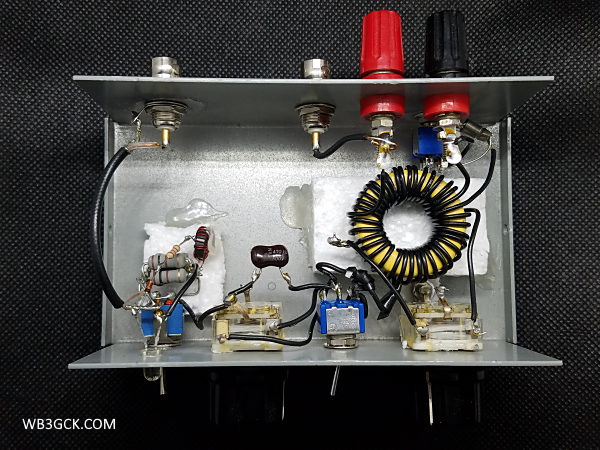
Another W6JJZ modification I used was the inclusion of a DPDT (center off) toggle switch to provide some flexibility with the input capacitor. Using this switching arrangement, I can select between one section of the capacitor, both sections in parallel, or both sections in parallel with a fixed 470pF mica capacitor. The extra input capacitance can sometimes be helpful on the lower frequencies.
The capacitors are poly film variable capacitors (2 sections @ 365pF each), which were originally purchased from Mouser Electronics. Unfortunately, Mouser no longer carries them, and I don’t know of another commercial source. I should have purchased a truckload of them when they were available! Similar capacitors with smaller values are still available if you look around.
The SWR bridge I used is a Dan Tayloe LED SWR indicator from a kit that was offered years ago by the Arizona scQRPions. It uses a resistive bridge circuit with a single LED to indicate a null when the bridge is balanced. For the 50-ohm resistors in the bridge, I substituted 2 100-ohm, 1-watt resistors. The bridge will handle a typical 5-watt QRP rig without flinching and could probably handle a bit more than that.
The whole thing was packaged in an enclosure which measures 3 x 5 x 2 inches. It certainly could have been built into a smaller package, but I had this enclosure on hand and decided to put it to use.
On the Air
To use the Z-Match, adjust the capacitors for a null in the background noise in your transceiver. That will get you close to a match. Then, switch in the SWR bridge, apply some RF, and tweak the capacitors for minimum brightness on the LED. There may be some interaction between the two capacitors, so you might have to go back and forth between them a time or two.
For an initial test, I hooked it up to the famous—in my mind, at least—WB3GCK Downspout Antenna. The little Z-match loaded up the downspout on 40 through 10 meters with no problems. On most bands, I could get the LED indicator to go completely out. On one or two bands, I couldn’t get it completely extinguished, but it did give a definite null. Double-checking with a second SWR bridge indicated that the SWR was 1.5:1 or less in this condition. While tuned up on 40 meters, I had a quick QSO with a station near Chicago from here in southeastern Pennsylvania with 3 watts.
Wrap-Up
This little Z-Match tuner was one of my favorite—and most useful—projects. It’s a great accessory for QRP rigs that lack an internal tuner or SWR meter.
73, Craig WB3GCK
©2000-2020 Craig A. LaBarge

An interesting build, Craig. However, I’ve been happy with my LDG Z-817 matched w/ my FT-817ND. I guess the lessons not learned building your z-match are my loss by taking the ‘easy way’ to tune my rig. Thanks for the write-up!
LikeLike
Thanks. I used the Z-Match with my FT-817 for several years until I bought the Z-817 tuner. Now, I mostly use my KX3 with it’s internal tuner. I guess I’m a bit spoiled now. I still use the Z-Match from time to time with some of my old, single-band rigs. It does a decent job with balanced feedlines. Stay safe.
LikeLiked by 1 person
Looks like L1 is a transformer. I see 12t and 17t for a total of 29t yet I see some additional turns at the bottom that go to ground. Would this be 8t?
I see on the other side, it shows 8t so this is why I assumed 8t. One side is primary and the other is secondary.
LikeLike
Hi Daniel: It’s hard to tell what exactly your referring to, but the 8-turn secondardy is bifilar wound (wound in between the bottom turns of the primary side). Looking at the inside view picture, the wire in the upper right going to ground is the bottom of the 29-turn primary. That’s the only wire that goes directly to ground. The wire next to it going to the black binding post connector is the bottom of the 8-turn secondary. It is only grounded when the S2 switch is in the “UNBAL” position. Looking at the variable capacitor on the bottom right, the wire on the right is going to the top of the 29-turn primary, and the wire on the left is going to the 12t tap. I hope this helps. 73, Craig WB3GCK
LikeLike
Hello,
Sorry for being ignorance. I want to build this. I have the parts. And I already drilled the aluminum case I got from Jameco. It is bigger than I need, but it gives me room. And parts like variable capacitors, switches, connectors, and LED are in the case now. Now, it is a matter for building the toroids and soldering the components point-to-point.
Is this what it should be?
The primary of the L1 transformer from top to bottom:
29t
17t (tap)
12t (tap)
0t And it is here which goes to ground.
The secondary of the L1 transformer has 8 turns wound within the primary turns which goes to balanced line, unbalanced line, and S2 switch.
— OR —
The part about 29t total confused me for the primary. Because there was the part at the bottom. Then I realized you maybe counting the number of turns total for each tap.
The secondary I can easily see 8t.
Primary From top:
12t.
5t tap.
12t tap.
0t and it is here where it goes to ground.
And 0t is the bottom of the L1.
Equals 29 turns total for the primary.
8 turns for the secondary wound within the bottom primary turns.
Sorry for being difficult. I have not done a lot of homebrewing. But I need a z-match for my QRP radios I built and are building. But I want to make sure I fully understand before I proceed. The rest should be easy.
And of course, the secondary goes to the balancing inputs, unbalanced coax, and S2 switch.
Thanks!
73 Daniel KK4MRN
LikeLike
200pF (60+140) poly film variable capacitors are still available in Germany:
https://www.box73.de/index.php?cPath=82_101
Or in Venezuela:
https://teslaelectronics.store/en/list/85-capacitor-variable-60140-pf.html
73 Markus HB9BRJ
LikeLike
Craig,
Poly variable dual 335pf and 20pf capacitors are available at https://www.mikeselectronicparts.com/product/variable-capacitor-335pf-20pf/ These can be combined to produce a 355pf dual cap.
I just built the Z-match and SWR bridge in this article. I just finished it last night, works well in bench testing. I challenged myself by “squeezing” it into a homebrew box made from copper clad PC board not much bigger than a QCX-mini. In retrospect I should have tried a T-130-6, but it’s done. Fun project. Thanks for the post Craig!
73, Steve W6WU
LikeLike
nice build for a clasdic tuner
john ve3ips
LikeLiked by 1 person
Nice build for a Tuner
BH4ESA
LikeLike