In a recent post, I wrote about an old antenna tuner I built about 25 years ago. Although a description of it has been online for decades, I never posted pictures of it. So, here it is.
I originally posted an article about this tuner on my QSL.net website under the title: A Simple and Flexible Tuner for QRP. Once my go-to transmatch for portable use, it had been on the shelf for quite a while. I hadn’t opened the case in 20 years, so it was a nostalgic walk down Memory Lane for me.
All of the parts used for this project came from my junk box or were re-purposed from other projects. This is the second tuner to inhabit this enclosure, so the variable capacitor and rotary switch were already in place.
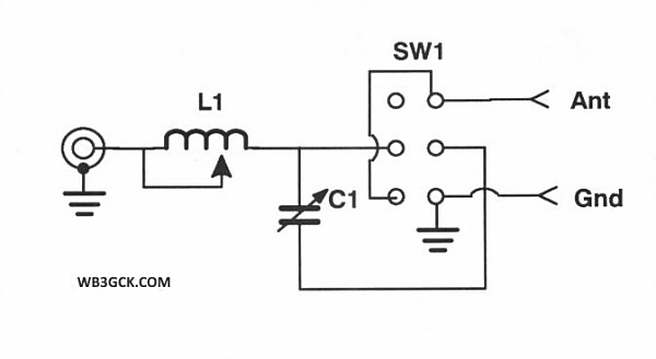
The coil is consists of 40 turns of enameled copper wire on a plastic 35mm canister. The wire appears to be 22 AWG. I wasn’t shooting for any particular inductance value; I just started winding turns. Based on the dimensions of the coil, the total inductance appears to be approximately 31 uH. I tapped it in 8 places and wired it to a rotary switch. I used two-sided foam tape to secure it to the bottom of the enclosure. I left the cap on the film canister so that the lid would press down slightly on it. This helps to securely hold the coil in place.

The variable capacitor was salvaged from an old radio by a friend of mine. It’s a two-section capacitor, totaling about 365 pf, according to my notes. I added a switch to select between one or both of the sections. Because the capacitor is sometimes in series with the coil, I used some thin fiberglass material to insulate it from the chassis.

To the best of my recollection, I purchased the aluminum box at Radio Shack back in the day. I finished off the project with some embossed labels made on an old Dymo label maker. They look tacky, but they’re still holding up after all these years.

After spending 15 or more years on the shelf, this funky-looking tuner has been seeing a lot more use lately. I mostly use it as an L-Match for end-fed wires. (I’ve only used the low impedance, series connection a few times over the years.) It’s a great portable tuner for QRP when weight isn’t a consideration.
I have the parts on hand to build a lighter L-match when I need to carry a tuner in my backpack. Until I find the time to put it together, I’ll keep using this funky old tuner.
73, Craig WB3GCK

When used with inductor and capacitor in series between input and output, all it can do is to modify the reactance of the load (probably including making the total reactance zero) but aside from losses the load resistance will not be changed.
It’s worth noting that by turning the unit around and connecting antenna to input side and transmitter to output side and using the L network, you can match lower impedances than 50 ohms.
All things equal, L networks have lower losses than any other antenna matching schemes. But for some highly reactive loads, an L network has to consist of two inductors or two capacitors instead of one inductor and one capacitor.
I discovered the utility of an L network when I was first licensed (W8EZE) at the age of fourteen. The rotary inductor inside my BC458 Command Transmitter and an external tuning capacitor liberated from a defunct AM BC receiver formed the L network. I tuned for maximum brilliance of a pilot bulb in series with the antenna. Later I did the same thing with another Command Transmitter on 80 m. I worked my first 80 m VK that way. A few years later I knew enough mathematics to understand why it worked.
LikeLike
Looks awesome , for 20 or more years, electronics, will always have a use some where, it just sad sometimes that as times change the basic things look so bulky, but the principle of application is always adaptable to even newest applications, thanks for sharing.
LikeLike