I needed another mini straight key like a hole in the head. With my fascination for these things, however, I just couldn’t help myself.
The key in question came from AliExpress and cost me about $18 USD. Although it has no markings on it, it appears to be from the same manufacturer as the QU-21C paddles I bought a while back. The basic design is the same as the QU-21C, and it came with identical packaging and accessories. After modifying the magnetic base, the paddles have served me well. So I took a chance on the look-alike straight key.
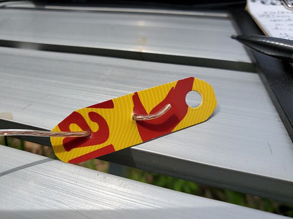
My no-name mini straight key from AliExpress during a recent portable outing. The key is magnetically attached to steel strips I glued to my clipboard.
Out of the box, the straight key’s contact spacing was a little wide for my taste. Using the included Allen wrench, I adjusted the key more to my liking. For a cheap key, it has a pretty good feel to it, and it keys cleanly.
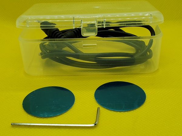
The accessories that came with the mini straight key. (Not shown is an adhesive rubber square that I attached to the bottom of the key.)
Based on my experience with the QU-21C paddles, I had some reservations about the highly polished square magnet on the bottom. However, since the motion of the straight key is the vertical plane instead of side-to-side, the magnet is less of an issue.
I used the key during a recent outing, and I had no major issues with it. I have some a couple of steel strips glued to my clipboard, and I stuck the key there. There was a little movement, but nowhere near as bad as the paddles. I just needed to make sure I didn’t get too vigorous with my keying. After I use them some more, I’ll decide if I want to modify them like I did with the paddles.
Most of the time I get what I pay for, but in this case, I think I got a decent product for the price. I let you know if my opinion changes with time.
When I bought the QU-21C Mini Paddles a while back, I wasn’t crazy about the small square magnet attached to the base. It didn’t seem to hold very well. When subjected to vigorous keying, the paddles would sometimes move side-to-side. I came up with a quick and dirty hack that resolved the issue for me.
A little backstory is in order. I’ve never been a big fan of “two-handed” keying; that is, holding the paddles in one hand while sending with the other. I modified a small clipboard by gluing two steel washers to it, such that they lined up with the two magnets in my Palm Mini paddles. The clipboard securely holds the paddles and gives me a nice writing surface for logging in the field. I’ve been using clipboards like this for about 10 years now.
In just a few minutes, I modified my QU-21C paddles to adapt them to my clipboards and make them more suitable for “single-handed” keying. The first order of business was to remove the square magnet from the bottom of the paddles. That was almost too easy. I wedged a knife blade between the base and the magnet, and the magnet popped right off.
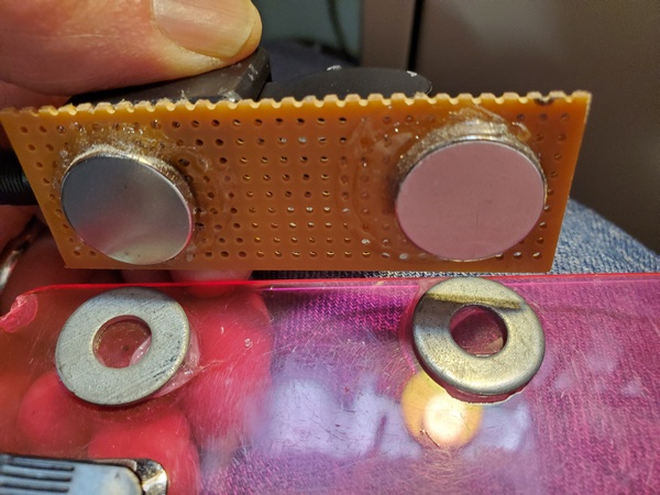
Magnets glued to the underside of the perf board to line up with the steel washers on my clipboard
Next, I took some perf board from my junk box and cut off a 3.5 x 1 inch piece. I used some Goop® adhesive to attach two magnets on one side of the board. I placed them so they had the same spacing as the magnets on my Palm paddles. Then I glued the QU-21C paddles to the other side of the perf board. Except for the drying time for the adhesive, I completed the project in about 10 minutes.
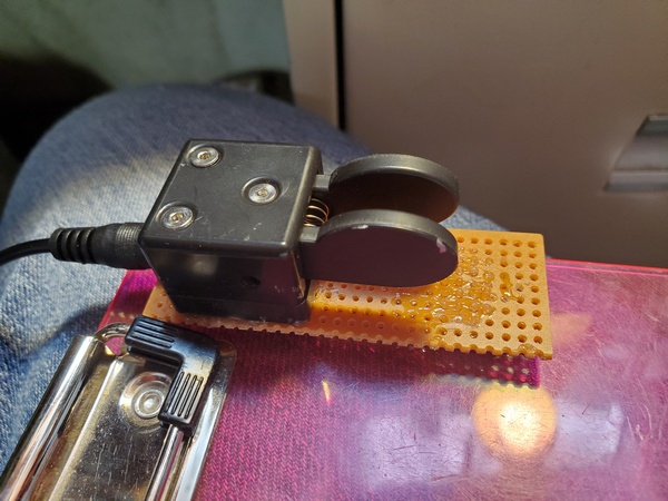
The QU-21 paddles glued to the perf board and ready for use
The magnets I used are really strong and probably overkill for this application. But, I had a bunch of them on hand, so I put them to use.
Admittedly, this cheesy little hack doesn’t look like much. If I feel ambitious sometime, I might come up with something more elaborate. Maybe something like the base I made for my little MS2 straight key. For now, though, this will suffice.
I’ve been toying with the idea of putting together a small radio kit based on my (tr)SDX or something similar, so I’ve been looking at small paddles to go with it. Browsing through eBay recently, I came across several listings for the QU-21C paddles. They were inexpensive, so I thought I’d order them and give them a shot.
These paddles are nothing new; they’ve been around for a few years. (I’m definitely no early adopter.) The QU-21C paddles are made in China and mine are marked with the brand name, Magic Rabbit. From other reviews I have seen, there may be other manufacturers. So, the quality and packaging may vary. I paid about $24 USD from a seller (iDrone) that ships from the U.S., but you can find them listed for less than $20, if you don’t mind waiting for a shipment from China.
Opening the package, I found the paddles are even smaller than I expected. The base is approximately .98 inch by .98 inch (25mm x 25mm) and 1 inch (26mm) tall. The overall length, including the paddles, is 1.9 inches (48.5mm). On my kitchen scale, the paddles weighed in at 1.25 ounces (34 grams). The paddles appear to be 3-D printed, but the quality is pretty good. The base of the paddles is magnetic, which is one feature that first drew my attention.
Magic Rabbit QU-21C paddles with the rubber pad attached to the magnet. The pad looks a little ragged around the edges, because I applied it, removed it, and then decided to put it back on. I messed it up a little in the process.
The package I received included:
Paddles with a magnet attached to the bottom
3-ft cable with 3.5mm stereo plugs on each end
Hex wrench for adjusting contact spacing
Two adhesive metal discs
Adhesive rubber pad
Plastic storage case that holds everything
Some of the accessories that came with it. The cable is inside the clear plastic storage box. The adhesive discs can be applied anywhere, so you can use the attach the paddles magnetically.
My first impression was that the contact spacing seemed a little wider than I like. I used the supplied hex wrench and adjusted the spacing until the contacts were completely closed. Then, I backed off a little.
I prefer a light spring tension on my paddles, but the spring in these paddles seems stiffer than I’m used to. Unfortunately, there’s no adjustment for that. So, I’ll just have to get used to using a little more force than my other paddles.
I’m not sold on the magnetic base, though. The square magnet is fairly strong, but it’s highly polished. So, the paddles sometimes have a tendency to slide when I’m sending. I applied the rubber pad that comes with it, but that seemed to offer only minimal improvement. For now, I just hold them in one hand while sending with the other.
I’ve actually thought about trying to remove the magnet altogether, since it appears to be glued on. At least, it wouldn’t be attracting every ferrous object that comes near it. But, for now, I’m just thinking about it.
The QU-21C paddles during a recent activation, along with my trusty Palm Mini paddles.
I had a chance to use the QU-21C paddles on a recent park activation. It didn’t take long to get used to them, and I had no issues with them at all. The paddles keyed reliably, without missing a single dit or dah.
Even with my spring tension and magnet gripes, I’m pretty happy with these paddles. These cheap paddles look like worthy candidates for field use. We’ll see how well they hold up over time.
It’s been a while since I’ve done a cheap speaker wire antenna, so here’s another one for you. Back in the early to mid-2000s, an antenna commonly referred to as the “No Counterpoise Antenna” was making the rounds on the Internet. I thought I might give it another look.
The No Counterpoise Antenna is either a 25-foot or 50-foot length of two conductor wire with half of one conductor removed. Essentially, it’s a radiator fed through a balanced line feeder. The 25-foot version is said to cover 20M through 10M, while the 50-foot version is supposed to cover 40M through 10M. It was usually connected to a balanced tuner of some sort or sometimes fed through a 4:1 balun. It was typically constructed from zip cord or speaker wire. So, this is perfect for another speaker wire project. (Actually, I built the 50-foot version years ago, but I don’t recall ever putting it on the air.)
A picture is worth a thousand words, so here goes:
I’ve seen this antenna sometimes referred to as a Zepp. A true Zepp is basically a half wave radiator with a quarter wave balanced line matching section. Unlike a true Zepp, the No Counterpoise Antenna is non-resonant, so I guess it’s actually “Zepp-ish.” Because it’s non-resonant, a tuner is required for this antenna.
I did some extensive research into the origins of this antenna. (OK… I just did a few Google searches.) Jeff Imel K9ESE came up with this design. I remember Jeff used to sell a high-quality version of the antenna on eBay. The reviews were generally positive.
Pete Millis, M3KXZ, is another name often associated with this antenna. I think that’s how I first came across it. Pete once made a phased array from two 25-foot versions.
In the August 2020 edition of Ozark QRP Banner, the Four State QRP Group’s newsletter, Terry Fletcher, WAØITP, had a nice write-up about it. He discusses his experience with both the 25- and 50-foot versions.
This antenna design has been around the block a time or two. So, there’s no innovation here on my part whatsoever.
Construction
I happened to have a 25-foot roll of #18 awg speaker wire on hand, so this time around, I opted to build…you guessed it… the 25-foot version.
Construction was about as easy as it gets:
I split the speaker wire halfway and cut off one side
Next, I twisted a loop at the end of the single wire and secured it with some Goop® adhesive. As an alternative, you could just tie a loop at the top or crimp a ring lug over the wire’s insulation.
I stripped and tinned the wires at the feedpoint and installed spade lugs. You can just strip and tin the wires, if you like.
To keep the speaker wire from splitting further, I put some heat shrink tubing a couple of inches up from the lugs. I also added a dab of Goop® in the middle of the antenna where one side of the wire was removed. All of this is completely optional.
Construction probably took me all of 15 minutes or so. That doesn’t include allowing the adhesive to cure overnight. However, the antenna was certainly usable without the adhesive and heat-shrink tubing I used. I’m just prone to overkill.
On the Air
To test the No Counterpoise Antenna, I drove down to Ridley Creek State Park (US-1414, KFF-1414). Using my drive-on mount, I supported the antenna from a 28-ft Jackite pole. I used a homebrew 4:1 unun at the feedpoint and ran 15 feet of coax into the cab of my truck to my KX3 (5 watts, CW). I used the long side of the antenna as the radiator.
I used my roll-on mount to support a 28-ft Jackite pole
Before I got started, I checked to see how the tuner in the KX3 would handle the antenna. The KX3 easily found a 1:1 match on all bands from 40M through 10M. Just for the heck of it, I tried 60M and 80M. The KX3 was able to find a good match on those bands, too. (That’s not too surprising, given that I once forgot to attach my coax to an antenna, and the KX3 still found a match.) I doubt this antenna would work well on 60M and 80M—but stranger things have happened. I wasn’t able to try it, but I’m sure the KX3 would be able to match it directly connected to the radio without the 4:1 and coax.
I used a 4:1 unun at the feedpoint
Band conditions weren’t very good, so this wasn’t an ideal test. Despite the mediocre band conditions, I logged 13 contacts during my short activation. Most of my contacts were on 40M. There was considerable fading on 30M and 20M, but I made a contact on each of those bands.
This was hardly a rigorous evaluation, but the 25-foot No Counterpoise Antenna got the job done. I need to give it another try, when conditions are better.
Anyway, if you have some speaker wire and a few minutes to spare, give this one a try and see what you think.
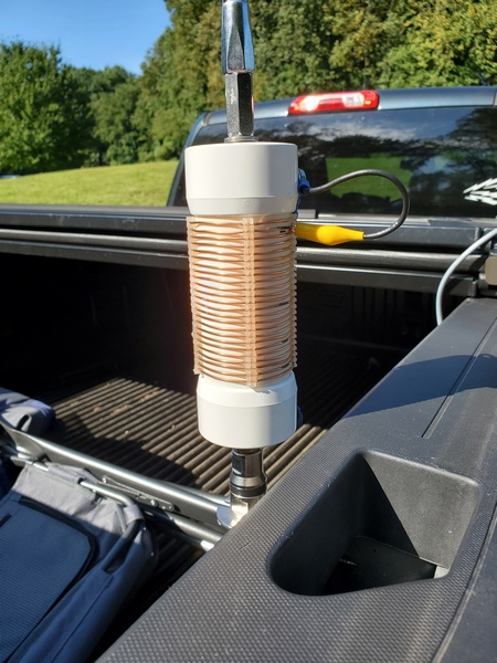
I had a chance to use the inexpensive whip I bought through AliExpress recently. While it performed well enough, I encountered a couple of minor quality issues. That’s certainly not surprising, given its $18 USD price tag.
Extending the whip, I noticed that two of the sections were pretty tight and took some effort to pull them out. Better tight than loose, I guess. Another issue is that the crimp that holds the mounting stud in the bottom section of the antenna was a little loose. When the antenna was fully seated in the mount, I could still rotate the antenna.
My $18 (USD) whip from AliExpress mounted on my homebrew loading coil
Because this whip is longer than a quarter wave on 20M, I didn’t extend the first section from the bottom. Using an antenna analyzer, I was seeing SWR readings similar to my MFJ-1979 whip. The SWR readings seemed stable. So, I guess the suspect crimp is making a good enough connection.
Band conditions seemed so-so this morning. Despite that, I logged 25 contacts on 40M and 20M in an hour, including three park-to-park contacts. I didn’t work any DX stations today, but I worked a station on the west coast in Washington on 20M.
Even with its issues, the whip did a pretty decent job this morning. It won’t replace my MFJ whip, but it will have a place in my antenna arsenal.
A while back, I ordered a 5.6M/18.4 foot. telescopic whip from a seller on AliExpress. I didn’t really need it, but having seen them on the Interwebs, I was curious to see what you get for $18 USD. Heck, at that price, why not take a chance?
You can find these whips all over AliExpress. (I have also seen them on Amazon for about $10 more.) One nice thing about them is they are 7.5 inches shorter than an MFJ-1979 when fully collapsed. So, it might fit in backpacks easier. The shorter collapsed length is due to having 14 telescoping sections compared to the MFJ-1979’s 10 sections. Because of its thinner metal and lack of a reinforced base, the AliExpress whip weighs 4.4 ounces/125g less than the MFJ whip. Of course, the other obvious advantage is the incredibly low cost.
There are some downsides though. The threads are metric (10mm), so you need an adapter to use it with a ⅜-24 mount. Fortunately, adapters are readily available as well. The other downside that I’ve noticed is that the metal they are made of is pretty thin. (More on that in a bit) The MFJ whip has a heavy stainless steel reinforcement at the bottom, while the AliExpress whip does not.
My antenna arrived from China about a week and a half later. It came wrapped in several layers of bubble wrap with a tough plastic outer wrap. I eagerly opened the package, but I was disappointed to see that the bottom section was damaged. It looked like either someone dropped something heavy on it or Big Foot stepped on it. As I mentioned previously, the metal is pretty thin.
While traveling half-way around the globe, this telescopic whip antenna encountered some rough handling.
When I finished uttering every expletive in my vocabulary, I contacted the seller through the AliExpress app and sent pictures of the damage. They promptly shipped out another antenna, and they didn’t want the old one back. So, I set the wounded whip aside, while I awaited its replacement.
The replacement whip arrived 6 days later, which is pretty impressive for a shipment from China. Happily, this shipment arrived intact. I would be remiss if I didn’t give props to the HUI BANG TE Store on AliExpress. Their customer support was top-notch.
When I get a chance, I’ll take the inexpensive whip out to a park to give it a go. I laid the AliExpress whip next to the MFJ-1979, and it looks like collapsing one section from the bottom on the AliExpress whip makes it about the same length as the MFJ.
I also have some ideas on how to straighten and reinforce the damaged whip to make it usable. That might be a winter project.
Whenever I buy parts for a project, I always buy one or two extras. Over the years, I’ve amassed a sizable collection of random parts. Some of it will never be used, but sometimes my collection of parts has just what I need for something I want to build. I like when that happens.
A while back I wrote about an old homebrew coil I resurrected and paired with a 12-foot telescopic antenna. The coil, while effective, was built to use with a much shorter whip and is larger than what I need. I scoured my junk box and came up with most of the parts I needed to build a scaled-down version.
I should note that I built this coil specifically to use with my old MFJ-1956 12-foot telescopic whip. In this configuration, this coil covers 40M through 17M. So, if you have a different whip or want to cover different bands, you’ll need to modify the design accordingly.
Completed loading coil. Used with a 12-foot telescopic whip, it tunes from 40M through 17M.
I used the old coil as a guide to determine the number of turns I needed to cover the bands of interest, adding two turns for good measure. Using an online shortened vertical calculator, I figured I would need about 13.4μH to load the 12-foot whip on the 40M band. Using an online coil inductance calculator, I estimated the total inductance of my coil to be 14.8μH. So, it covers 40M with a turn or two to spare.
The new coil assembly measures 8.25 inches end-to-end, making it 2.25 inches shorter than the old coil. While it’s about 3.3 ounces lighter than the old coil, this new coil still weighs in at a hefty 10.8 ounces.
Parts List
With a few exceptions, my junk box provided the parts I needed to build the coil.
5-3/8 inches of 1.5 inch PVC pipe
(2) PVC end caps for 1.5 inch PVC pipe
(4) pieces of nylon grommet edging, 3.25 inches each. (The material I used has about 8 notches per inch)
16 gauge bare copper wire, approx. 12.5 feet
(1) 3/8-24 coupling nut, 1-1/8 inches long
(1) 3/8-24 x 1-1/4 inch stainless steel bolt (bottom mounting stud)
(1) 3/8-24 x 1 inch stainless steel bolt (top bolt)
3/8 inch flat washers & lock washers
(2) #10 x 3/4-inch self-tapping screws
Approx. 6 inches of RG-174 coax
Small alligator clip
Misc: ring lugs for ⅜-inch & #10 screws
Construction Notes
As shown in the accompanying photo, I drilled the end caps to accommodate the ⅜-24 bolts. The 1-1/4 inch bolt was used for the bottom of the coil, along with a flat washer and a lock washer. The 1-inch bolt was used for the top, along with flat washer, lock washer, and the coupling nut.
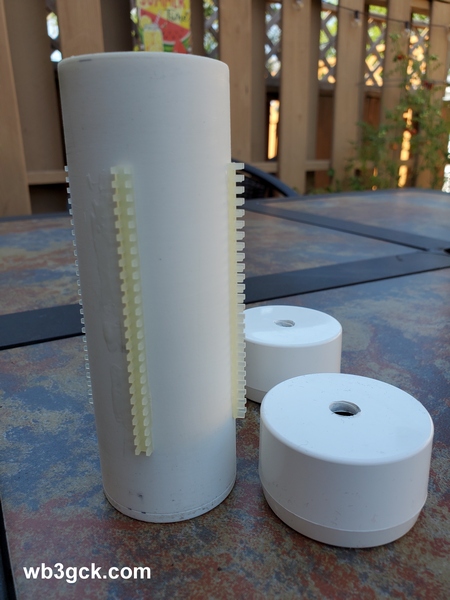
This is the coil form with the four strips of grommet edging glued on. The ends were drilled to accommodate the 3/8-24 bolts.
The coupling nut was one item I didn’t have in my junk box. My local hardware store is well-stocked, but they didn’t have them with the ⅜-24 thread. I eventually found what I needed on Amazon. It was a little pricey, but I didn’t have any better options at the time.
After cutting the PVC pipe to length, I temporarily installed the end caps. Then, I cut four pieces of the grommet edging to length and glued them on, using Goop® adhesive. Unfortunately, I can’t provide a part number and source for the edging. A local QRPer, Ron Polityka WB3AAL (SK), gave me several pieces many years ago. I’m pretty sure Panduit was the manufacturer. My stash was nearly depleted, but I had enough left for this project.
Before assembling the end caps, I made two short jumpers, each with a ⅜-inch ring lug on one end, and a smaller ring lug on the other. Then I tightened everything up. I left about a ½ inch of thread on the top bolt to go into the coupling nut. I was careful to ensure that my whip antenna would fully thread into the coupling nut.
Before winding the bare wire on the coil form, I installed a ring lug on one end. I drilled a pilot hole in the side of the lower end cap and used a self-tapping screw as a connection point. When you wind the wire on the coil form, try to get the turns as tight as you can. (I didn’t do as good a job winding the coil as I would have liked.) Once I finished winding the coil, I cut the wire to length and installed a ring lug. I used some more Goop adhesive on the grommet edging to hold the turns in place.
The last step was to build the clip lead. For this, I used a piece of RG-174 coax. There’s nothing magical about the RG-174; stranded hookup wire would be fine. I used RG-174 primarily because of its flexibility, plus the shield would be a good RF conductor. (The center conductor was unused.) I crimped and soldered a ring lug to the braid on one end, and soldered an alligator clip to the braid on the other end. Then I used another self-tapping screw on the top end cap to connect everything together.
On the Air
I wrote about my initial tests of the coil in a previous post. Using an antenna analyzer, I determined where to place the tap for each of the four bands. I then used a permanent marker to mark these locations on the coil, so I can quickly change bands without resorting to the antenna analyzer.
This is the completed loading coil installed on my truck for a POTA activation.
With the antenna mounted on my truck, the SWR is higher than I would like on 40M and 30M. This is not unlike other shortened, base-loaded verticals I’ve used in this configuration. An additional counterpoise wire or two might help. Also, grounding the bottom of the coil and feeding it a couple turns up from the bottom would provide a precise match on the lower bands. I’ve used that technique in the past. That configuration , however, is a bit more complicated to implement, given the way I plan to use this coil. So, I just use a tuner to keep the radio happy, and the antenna seems to work fine.
Wrap-up
My older, larger coil worked fine; so technically, this project was unnecessary. But, since I had most of the parts on hand, what the heck. It was a fun project, and I’m sure it will see a lot of use in the future.
Over the past couple of years, some knee issues have slowed me down. My new knee joint resolved those issues, and life is getting back to normal—as normal as my life gets, I suppose. Anyway, I’m planning to get back to doing some light hiking this year as the weather improves. With that in mind, I bought a new backpack to use on day hikes.
For the past four years, I have been using the Rambler sling pack from Red Rock. It has been—and still is—a great backpack. It has plenty of storage for hauling a radio and accessories out to the field, and it is one sturdy, well-built pack. My only issue with it is that it is a sling pack. For short trips, it’s fine. But, for longer trips, having all the weight on one shoulder feels a bit “lopsided” to me. If I could have the same pack with two shoulder straps, I would be a happy camper (hiker).
A while back, I came across the Wakizashi backpack from Samurai Tactical and saved it to my Amazon wishlist. The Wakizashi is similar in size to my Rambler sling pack. While it has fewer storage pockets than my sling pack, it has more than enough storage for my needs. (I tend to carry too much stuff with me anyway.)
When I purchased it, the Wakizashi backpack in black was selling for a mere $24 (USD). (Other colors are available at slightly higher prices.) For that price, if I didn’t like it, I could always give it to one of the grand-kids. The average ratings were 4.6 out of 5, so I took a chance and placed an order.
I should also note that I have no financial interest here; I paid for the backpack with my own funds. Also, the Amazon link above is not an affiliate link.
Amazon delivered the pack to a neighbor’s porch a few days later. I had to wander the neighborhood in the rain to find it. Not cool, Amazon.
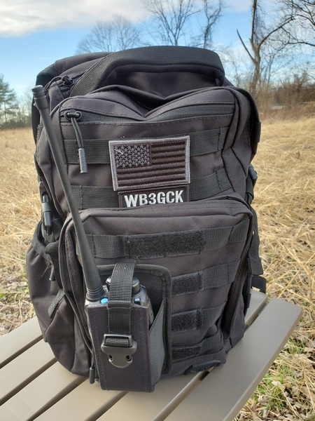
I wasn’t expecting much for a $24 backpack, but I was pleasantly surprised. For a cheap backpack, it seems well built. A few of the many reviews complained of poor stitching and general issues with quality. I saw none of that in the item I received. Mine was well-built, and the material appears to be durable enough.
Samurai Tactical Wakizashi backpack. The patches and HT pouch were added by me.
The pack measures 17.1 x 11.1 x 6.1 inches with a capacity of 24 liters. There’s a large main compartment and a smaller admin compartment. There are also two smaller compartments near the top of the pack. A side pouch is large enough for a water bottle, and there is plenty of MOLLE webbing on the sides and back. If you’re so inclined, it accommodates a hydration bladder and has a hydration port at the top of the bag.
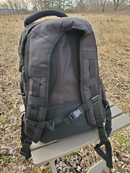
Samurai Wakizashi backpack shoulder and sternum straps.
Although the Wakizashi backpack has fewer compartments than my sling pack, there is enough storage to accommodate everything I normally carry in the field. Besides the radio gear, I always carry a small first aid kit, emergency poncho, headlamp, and a few other emergency items. The main compartment is a bit larger, so things that present a tight squeeze in the sling pack fit easily in the Wakizashi.
I’ve been using this pack for the past couple of months now with no issues. How well it holds up in the long term remains to be seen. For now, anyway, I’m happy with this budget backpack.
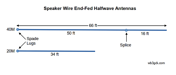
A while back, I challenged myself to see what kind of antennas I could make from a cheap 50-foot roll of two-conductor speaker wire. This time I made a couple of end-fed halfwave wires for the 40M and 20M bands.
My aim with these projects is to make (nearly) full use of the 50 feet of speaker wire. I figured that would be enough for 66-foot and 34-foot radiators for the 40M and 20M bands, respectively. These dimensions work with the Hendricks SOTA Tuner (now sold by Pacific Antenna) I planned to use with them.
Construction couldn’t be more simple:
Starting with 50 feet of speaker wire, separate the conductors.
Cut one of the wires into two lengths, 34 and 16 feet.
Splice the 16-foot wire onto the 50-foot wire. Now you have wires that are approximately a halfwave on 40M (66 feet) and 20M (34 feet).
I added spade lugs to one end of each wire.
I used pieces of a used gift card to make end insulators that would allow for adjustments if needed. (See photo)
Speaker Wire EFHW Antenna diagram
Of course, you’ll need an antenna coupler to match these wires to your rig. The SOTA Tuner I used worked fine, but each wire operated only on a single band. I cheated a bit and used some other scrap wire to make two short counterpoise wires, 5 feet for 40M and 3 feet for 20M. Of course, you could always use the 34-foot wire as a counterpoise for the 66-foot wire if you’d like.
An improvised end insulator made from an old gift card. I used this so I could shorten the wire, if needed, by folding it back on itself.
I haven’t tried it yet, but an L-network transmatch should allow the 66-foot wire to work on 40M, 20M, and 10M. A 49:1 transformer might also give you multiple bands with the 66-foot wire. You’ll likely need to adjust the length to obtain a match. You’re on your own here.
In the field, the SOTA Tuner provided a good match on both wires. I used the 66-foot wire as an inverted vee and the 34-foot wire as a sloper. I had no trouble making contacts on both bands with 5 watts.
Of course, you could build these antennas with any old wire. After all, it’s just wire. But, I enjoy the challenge of being constrained by the 50 feet of speaker wire.
I have more speaker wire and more antenna ideas, so you’re going to be subjected to more of these crazy projects in the future.
In a previous post, I mentioned an antenna of mine that went missing. The antenna in question was a variation of my old Dollar Store Special. After I built a replacement, I found the original in my truck. No problem; as the name suggests, it wasn’t a huge monetary investment. This antenna is just another example of what can happen with some extra speaker and too much time on my hands.
The original Dollar Store Special (circa 2005) was the first of several projects to see if I could build a usable antenna from a 50-foot length of inexpensive speaker wire. The resulting antenna was a 50-foot radiator and some counterpoise wires configurable for 40M, 30M, and 20M. I used one of these for years as a backup antenna. As with all random wire antennas, it requires a tuner and, of course, some way to get one end up in the air.
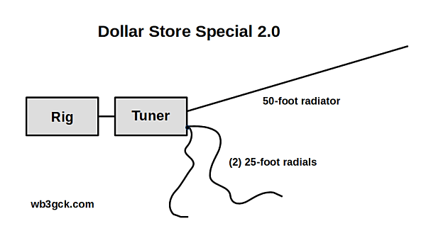
For this version, I went with a 50-foot radiator and two 25-foot radials. Besides being more simple to construct, it adds a little more flexibility. Space permitting, I can use the 50-foot wire in an inverted L, inverted V, or sloper configuration. When I need a quick way to get on the air, I can use a 25-foot radiator with a 25-foot counterpoise. (Elecraft documentation often recommends the 25-foot wires as a simple field antenna. [1][2])
My updated Dollar Store Special. In addition to this configuration, I sometimes use one of the 25-foot wires as the radiator and the other as a counterpoise.
I refer to this antenna—with tongue firmly planted in cheek—as the Dollar Store Special 2.0. That makes it sound like a bigger deal than it actually is. I should also note that I can no longer get speaker wire at my local dollar store. I have to spend a few dollars more now, but I kept the name anyway.
Construction is as easy as it gets:
Get a 50-foot length of two-conductor speaker wire. I use some inexpensive 24 gauge wire.
Separate the two conductors.
Cut one of the 50-foot wires in half.
I added a spade lug on one end of each wire and made a small loop in the other end.
I also added some Goop® sealant/adhesive to hold the end loops together and provide some strain relief to the spade lugs.
The 50-foot radiator and two 25-foot radials cover 60M through 10M using my KX3’s internal tuner. Feeding it through a 4:1 unun, I can cover 80M through 10M. A 9:1 unun works well with this length also.
With a 25-foot radiator and a single 25-foot radial, my KX3 covers 40M through 10M with no problems. Adding in a 4:1 unun makes this a Rybakov 806 antenna that covers 60M through 10M. If you’re so inclined, you could partially unroll the 50-foot wire and use it as a second radial.
These results, of course, are highly dependent on the tuner you’re using. There’s nothing special about the 50-ft length. You can trim the radiator back to a length that provides an easier match. I stayed with the 50-foot length since I wanted to make use of the entire pool of speaker wire for these projects. Go with whatever works for you.
I’ve had good results with both configurations, and I have been impressed with the 25-foot radiator and 25-foot radial configuration. Although it’s slightly compromised on 40M, it seems to get out pretty well.
There’s nothing at all magical about this antenna; after all, it’s just three pieces of cheap wire. However, it makes a decent backup—or even a primary—antenna kit for portable use.
As I was writing this, I jotted down two more ideas for speaker wire antennas. Somebody stop me!