Whenever I buy parts for a project, I always buy one or two extras. Over the years, I’ve amassed a sizable collection of random parts. Some of it will never be used, but sometimes my collection of parts has just what I need for something I want to build. I like when that happens.
A while back I wrote about an old homebrew coil I resurrected and paired with a 12-foot telescopic antenna. The coil, while effective, was built to use with a much shorter whip and is larger than what I need. I scoured my junk box and came up with most of the parts I needed to build a scaled-down version.
I should note that I built this coil specifically to use with my old MFJ-1956 12-foot telescopic whip. In this configuration, this coil covers 40M through 17M. So, if you have a different whip or want to cover different bands, you’ll need to modify the design accordingly.

I used the old coil as a guide to determine the number of turns I needed to cover the bands of interest, adding two turns for good measure. Using an online shortened vertical calculator, I figured I would need about 13.4μH to load the 12-foot whip on the 40M band. Using an online coil inductance calculator, I estimated the total inductance of my coil to be 14.8μH. So, it covers 40M with a turn or two to spare.
The new coil assembly measures 8.25 inches end-to-end, making it 2.25 inches shorter than the old coil. While it’s about 3.3 ounces lighter than the old coil, this new coil still weighs in at a hefty 10.8 ounces.
Parts List
With a few exceptions, my junk box provided the parts I needed to build the coil.
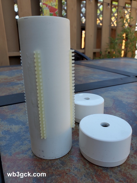
- 5-3/8 inches of 1.5 inch PVC pipe
- (2) PVC end caps for 1.5 inch PVC pipe
- (4) pieces of nylon grommet edging, 3.25 inches each. (The material I used has about 8 notches per inch)
- 16 gauge bare copper wire, approx. 12.5 feet
- (1) 3/8-24 coupling nut, 1-1/8 inches long
- (1) 3/8-24 x 1-1/4 inch stainless steel bolt (bottom mounting stud)
- (1) 3/8-24 x 1 inch stainless steel bolt (top bolt)
- 3/8 inch flat washers & lock washers
- (2) #10 x 3/4-inch self-tapping screws
- Approx. 6 inches of RG-174 coax
- Small alligator clip
- Misc: ring lugs for ⅜-inch & #10 screws
Construction Notes
As shown in the accompanying photo, I drilled the end caps to accommodate the ⅜-24 bolts. The 1-1/4 inch bolt was used for the bottom of the coil, along with a flat washer and a lock washer. The 1-inch bolt was used for the top, along with flat washer, lock washer, and the coupling nut.
The coupling nut was one item I didn’t have in my junk box. My local hardware store is well-stocked, but they didn’t have them with the ⅜-24 thread. I eventually found what I needed on Amazon. It was a little pricey, but I didn’t have any better options at the time.
After cutting the PVC pipe to length, I temporarily installed the end caps. Then, I cut four pieces of the grommet edging to length and glued them on, using Goop® adhesive. Unfortunately, I can’t provide a part number and source for the edging. A local QRPer, Ron Polityka WB3AAL (SK), gave me several pieces many years ago. I’m pretty sure Panduit was the manufacturer. My stash was nearly depleted, but I had enough left for this project.
Before assembling the end caps, I made two short jumpers, each with a ⅜-inch ring lug on one end, and a smaller ring lug on the other. Then I tightened everything up. I left about a ½ inch of thread on the top bolt to go into the coupling nut. I was careful to ensure that my whip antenna would fully thread into the coupling nut.
Before winding the bare wire on the coil form, I installed a ring lug on one end. I drilled a pilot hole in the side of the lower end cap and used a self-tapping screw as a connection point. When you wind the wire on the coil form, try to get the turns as tight as you can. (I didn’t do as good a job winding the coil as I would have liked.) Once I finished winding the coil, I cut the wire to length and installed a ring lug. I used some more Goop adhesive on the grommet edging to hold the turns in place.
The last step was to build the clip lead. For this, I used a piece of RG-174 coax. There’s nothing magical about the RG-174; stranded hookup wire would be fine. I used RG-174 primarily because of its flexibility, plus the shield would be a good RF conductor. (The center conductor was unused.) I crimped and soldered a ring lug to the braid on one end, and soldered an alligator clip to the braid on the other end. Then I used another self-tapping screw on the top end cap to connect everything together.
On the Air
I wrote about my initial tests of the coil in a previous post. Using an antenna analyzer, I determined where to place the tap for each of the four bands. I then used a permanent marker to mark these locations on the coil, so I can quickly change bands without resorting to the antenna analyzer.
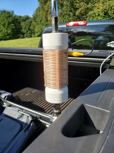
With the antenna mounted on my truck, the SWR is higher than I would like on 40M and 30M. This is not unlike other shortened, base-loaded verticals I’ve used in this configuration. An additional counterpoise wire or two might help. Also, grounding the bottom of the coil and feeding it a couple turns up from the bottom would provide a precise match on the lower bands. I’ve used that technique in the past. That configuration , however, is a bit more complicated to implement, given the way I plan to use this coil. So, I just use a tuner to keep the radio happy, and the antenna seems to work fine.
Wrap-up
My older, larger coil worked fine; so technically, this project was unnecessary. But, since I had most of the parts on hand, what the heck. It was a fun project, and I’m sure it will see a lot of use in the future.
73, Craig WB3GCK

Craig, I am curious about the idea of connecting the coax shield to the radials and the coax center conductor a few turns up the coil. How do you determine exactly where to connect the coax center conductor?
LikeLike
John: I used a variable tap, since it usually varies by band. For one antenna I used to use, I needed a cheat sheet to show the settings for the two taps. It works great, but is a bit more complicated to set up.
LikeLike
Ok thanks Craig. I will give it a try. When I’m using my coil loaded whip on my truck (similar to your arrangement) the best SWR I get on 20m is 1.7:1. The same antenna mounted on the ground with radials gives me 1:1 (both using an auto tuner). There are situations where I can’t put down radials – such as parking lot POTA activations where the truck itself is the counterpoise. Your technique gives me another adjustment to play with.
LikeLiked by 1 person
Hmmmmm… the grommet edging looks to be the hardest part to find. Since you’ve used up your supply, maybe it won’t be worth visiting your house in the dead of night and testing the doors and windows. 🙂
MANY Thanks for the construction notes.
73 N4REE, Bob
LikeLike
Thanks, Bob. You can find the grommet edging online, but usually in ridiculously large quantities. I’m glad I used up my supply, so I don’t have to worry about you testing my doors and windows. 😄
73, Craig WB3GCK
LikeLike
Excellent construction techniques Craig. I had a chuckle, like you I often buy double of what I need in parts. You never know when you will need them!
Thanks for sharing.
73, Andrew VK1AD
LikeLiked by 1 person
Hey, the coil build is awesome and nice use of a shorter whip to not hit as many tree branches
LikeLiked by 1 person