I’ve been intrigued by the half-square antenna for some time now. I don’t have the real estate to put one up at home, so I built one for portable use. Like my other speaker wire projects, this antenna is built from a 50-foot length of cheap, two-conductor wire.
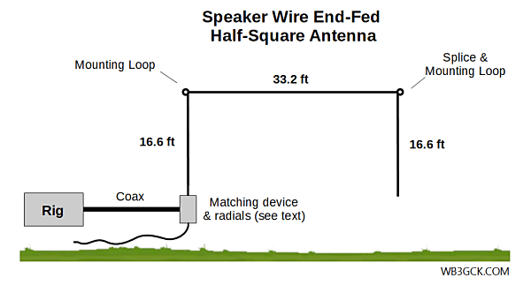
You can think of the half-square as two quarter-wave verticals spaced a half-wavelength apart. It provides some gain over a quarter-wave vertical and has a low take-off angle. The half-square has a bi-directional pattern with lobes broadside to the antenna and nulls off of the ends.
Normally, the half-square is fed with coax at the top of one of the vertical elements and functions as a single-band antenna. The coax should be kept perpendicular to the vertical leg, to avoid interaction. That arrangement, however, would be somewhat awkward for a portable antenna.
For expediency in the field, I went in a different direction. I decided to feed it at the bottom of one of the vertical legs, which is a high impedance point. I use a 9:1 unun to reduce the high input impedance to something easier for a tuner to handle.
I designed this antenna for the 20M band, but I wanted to use it on other bands as well. By using the 9:1 unun to feed the bottom of the antenna, I’m able to squeeze some more bands out of it. A tuner is required, of course.
Materials
Here’s what I used to build it:
- 50 feet of two-conductor speaker wire
- (1) Spade lug
- (4) small zip ties
- Goop® sealant/adhesive (or similar)
Construction
Refer to the accompanying diagram to help make sense of the following steps.
- Separate the speaker wire into two 50-ft wires
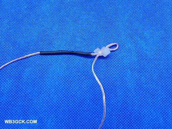
- On one of the wires, install a spade lug at one end. This will be the connection to your matching device)
- From the spade lug, measure up 16′ 7.2″ and make a small loop using two small zip-ties.
- From the second wire, cut a length that is about 16′ 9″ or so.
- Strip and splice the smaller wire to the end of the larger wire. After soldering it, I covered the splice with heat-shrink tubing.
- Next to the splice, make another small loop, using two zip-ties.
- At the end of that wire, twist the wire to form an attachment loop. When you do this, make sure you have 16′ 7.2″ from the splice to the attachment loop.
- I applied some Goop® adhesive to the loop at the end of the wire to hold it together. I also added Goop® to each of the other attachment loops.
- As is my usual practice, I added some Goop® to where the wire enters the spade lug to add some strain relief.
- At this point, the antenna is finished. You can, however, cut the leftover wire in half to make two radials for 20M (approximately 16 feet, give or take). I installed a spade lug on each of these wires and twisted the other ends to make a small loop. You guessed it; I put Goop® on these wires, as well.
Matching
[Update (6/17/2020) – After initially publishing this post, I received some great feedback from readers. As a result, I have updated, clarified, and expanded this section.]
For my first couple of outings with this antenna, I used a 9:1 unun as a quick and dirty way to get it on the air. I run about 18 feet of RG-8x coax from the unun to the radio. There’s nothing particularly critical about the coax length, but I would recommend a minimum of 16-feet for 40M and up. The exact length of the radials isn’t critical either since they’re laying on the ground. In fact, you can probably use the antenna without them. In this case, you’re relying on the coax shield for the counterpoise.
While the 9:1 worked fine, there are more efficient ways to match this antenna. I plan to continue experimenting with other methods to match the high-impedance input on 40M and 20M.
I haven’t tested them myself, but the end-fed halfwave tuners from Pacific Antenna and QRPGuys should work on 20M and 40M. They use a parallel resonant circuit and are designed to match an end-fed halfwave (EFHW) antenna.
An EFHW transformer, like the ubiquitous 49:1 transformer, should also work. You will likely need to do some pruning on the antenna to get the SWR where you want it.
Finally, a simple L-Match antenna tuner with a tapped inductor in series and a variable capacitor across the output looks like it may be the best solution for me. It should handle the high impedances on 40M and 20M, and work on other bands like a random wire tuner. This will definitely be part of my next round of experiments.
Deployment
Deploying this antenna is a snap and takes me about 5 minutes. I use two collapsible poles to support it. I attach one corner to a partially-extended 28-foot Jackite pole. The feed point of the antenna is about 3 feet off the ground.
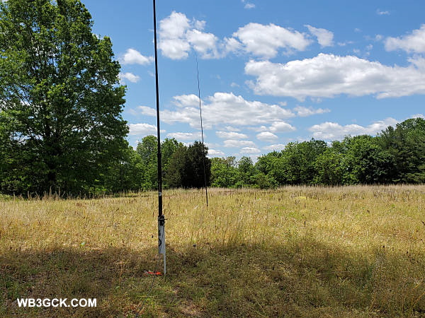
I use a 20-foot Black Widow pole (actual length about 19.5 feet) to support the other end. I support this pole with an appropriately-sized screwdriver shoved in the ground. The handle of the screwdriver fits snugly inside the bottom section of the pole. After attaching the other corner of the antenna to top of this pole, I extend the pole and remove the bottom cap. Next, I walk the pole back until the horizontal section is taut. Then, I just shove the screwdriver in the ground and place the pole over it.
With appropriate trees nearby, you might be able to eliminate one or both of the poles. I’m not usually that lucky.
Results of Field Testing
I was pleased with the results of my initial field tests with the half-square. The internal tuner in my Elecraft KX3 was able to load the antenna from 80M through 6M. (Since the antenna’s input impedance is low on 80M, I wouldn’t recommend using the 9:1 there.) The SWR was 1.2:1 or better on all bands with the tuner.
During my first outing with the half-square, I was able to make contacts on 40M, 20M, and 15M at 5 watts with no difficulty. The antenna is a half-wavelength on 40M, and it appears to play well on that band. I had numerous Reverse Beacon Network spots on 40M showing a signal-to-noise of 20db or better.
I also used it in the field during a recent QRP contest with similar results. Signals were strong on 40M, and I worked Georgia and Quebec on 20M.
This was hardly a rigorous scientific evaluation, but I’m happy with this antenna so far. One of these days, I’d like to do some modeling to see what the radiation patterns look like on the various bands. In the meantime, I’ll do some more experimenting with impedance matching.
Wrap-Up
This was an easy and fun project. It certainly made good use of a roll of cheap speaker wire. After using this antenna in the field a couple times, I have officially added it to my arsenal of portable antenna options.
73, Craig WB3GCK

When you say “9:1 unun” do you mean one with a 3:1 turns ratio or one with a 9:1 turns ratio (and thus something near 81:1 impedance ratio)? On 20 m, 40 m, 15 m, and 10 m the input impedance at the feed point should be quite high, so something higher than a 9:1 impedance ratio might reduce losses on the length of coax.
By removing the unun you’d make the antenna usable on 80 m where it would have a rather low input impedance; stepping down the impedance further with a unun seems like a bad idea. On this band you’d want a much better radial system than you’ve got, else losses in the ground system would be quite high. Since the high current portion of the antenna would be the part near the feedpoint, what you’d have would be an extreme example of an inverted-L.
As to pattern, I’d think that on 20 m the currents in the vertical sections would be in phase so the antenna would have low-angle radiation broadside with good nulls in the direction of the horizontal wire portion. On 40 m it would have nearly omnidirectional high-angle radiation typical of all cloud-burners; the currents in the vertical sections are out of phase so what little vertically polarized radiation the antenna produced with such low current in those end sections would give a bit of end-fire directivity while radiation from the horizontal portion (the lion’s share) would mostly go straight up because the horizontal part isn’t even 1/4 wave high. On 15 m the currents in the two vertical sections are again out of phase but their separation is about 3/4 wavelength so the antenna would become an end-fire array with probably pretty good low angle radiation. There would be some radiation from the horizontal portion too, filling in the nulls somewhat because now the horizontal portion is nearly 1/2 wave up. On 10 m the currents in the two vertical sections would be in phase again, and with a separation of about 1 wavelength I wouldn’t think there would be much directivity. However currents in the left and right halves of the horizontal section are out of phase and their centers are 1/2 wave apart so that would give a bit of end-fire directivity, especially since on 10 m the horizontal part is more than 1/2 wave up.
This is no substitute for a real pattern analysis but it’s a start.
LikeLiked by 1 person
David: Many thanks for your detailed analysis. I’m using 9:1 impedance transformation. It’s not optimal, but for casual operating in the field, it has been useable. I have a 49:1 that I will have to try. 73, Craig WB3GCK
LikeLike
Great work! I have done something similar with an EFHW match box I made. I setup the wire and feed it through the matchbox on one in. The match is adjusted to tune the antenna for minimal SWR. I use a counterpoise only about 1m long and have an RF Choke right at the feed point. Works great in several type of configurations including the half square.
LikeLiked by 1 person
Hi Craig, excellent write up, thanks for sharing. For multiband use, you could substitute the 9:1 unun with QRP L-Match. Agree, it’s all about personal operating choice 🙂
73, Andrew VK1AD
LikeLiked by 1 person
Thanks for the kind words, Andrew. Funny you should mention the L-match. I was thinking about going that route in situations where I’m able to position the radio within arm’s length of the antenna feedpoint. I’ll give it a go next time I use this antenna. Yep, with the 9:1, I traded some efficiency for convenience. 73, Craig WB3GCK
LikeLike
Nice article.
I love experiments like what you’ve done. Start with a phased 1/4 wave in mind and morph up to an end-fed full wave. And then make it work. Cool.
Your original idea of a half-square is a take off of what I had on my truck for a CB, except the antennas were fed from a standard mobile mount and phase with coax. I wonder if you could turn the half square over, having the phasing line between the quarter-wave elements just off the ground. Might be interesting to try.
Recently I’ve turned from playing with quarter-wave wire antennas on 40 and 80 (loaded) to assembling the stuff to make an EFHW for 20 with an air-wound inductor and capacitor as an auto-transformer/un-un. I have an MFJ pole that extends to 33 ft, and mounts on the back of my truck–while parked LOL. Fed without the un-un it is quarter wave on 40.
73 de N6BVZ/4 wil
LikeLike
I like the idea of the L-match. Feeding high-impedance antenna is art and magic 🙂 While at low impedance it seems to be quite easy to direct the current where you need it to do the work, at high impedance I am always afraid of power leaking through stray capacitances, nearby coupling etc. How about counterpoise? I saw VK3YE using some kind of aluminum mat, but how about on-the-ground radials (e.g. 15x 2 meters, like for a vertial), tuned radials or a halfwave single counterpoise? Did anybody try?
LikeLike
Craig, great post. How did you secure the leg with the splice and mounting loop? I’m not sure how I missed that in the “Speaker Wire Half-Square Antenna” article.
LikeLike
Hi Doug. I just used a reusable velcro cable tie to hold that wire in place against the pole. Thanks for your kind words about the post. 73, Craig WB3GCK
LikeLike