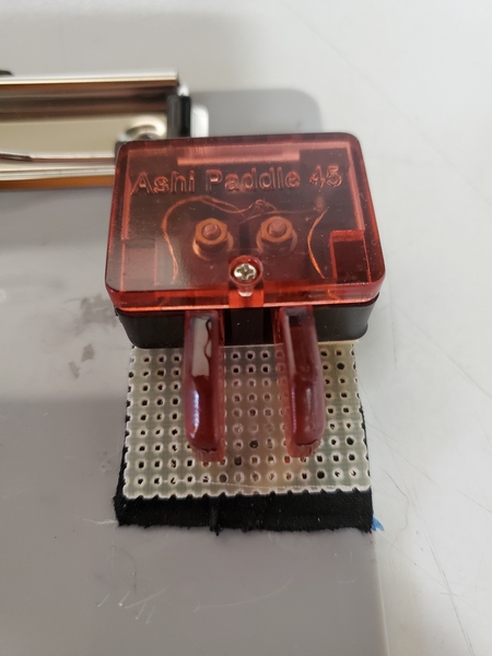
I bought the Ashi Paddle 45 from N6ARA Electronics last year. While I like the paddles a lot, the magnetic mount wasn’t strong enough for the way I operate. I did a quick and dirty mod to address that issue.
I’m not a huge fan of holding paddles in one hand while keying with the other. I have operated like that and probably will again, but that’s not my preferred technique. My preference is to use a small clipboard with steel strips glued on and a magnetic base on the paddles. Of course, this arrangement only works if the paddles have magnets strong to keep them from moving. This is a problem with some portable paddles.
As with many portable paddles, the Ashi paddles are small and lightweight. As a result, the magnets on the included attachment are small and confined to the bottom of the base (out of necessity). This gives the paddle levers some mechanical advantage, allowing the base to slide side-to-side with vigorous keying.
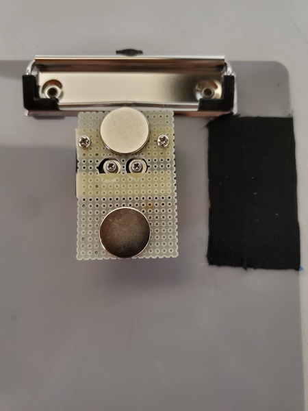
With the Ashi paddles, I used a mod similar to what I used for my QU-21 paddles. As luck would have it, I had a scrap piece of fiberglass perfboard that was just about the perfect size. What are the odds of that? Then, it was a simple matter of drilling a few holes, using the original magnetic mount as a template.
The paddles attached to my clipboard
Initially, I used just the two original screws to attach the board, but I could feel a little vertical flexing when I used the paddles. I finally added a couple of strips of two-sided foam mounting tape, and that seemed to do the trick.
The underside of my quick and dirty mod. The black rectangle to the right are the steel strips covered with hockey grip tape.
The other issue I run into is highly polished magnets. Even though I used some powerful magnets, their slick finish still allowed a little sliding. While searching for something thin that would provide a little friction, I stumbled across hockey grip tape. This is the cloth tape used on hockey sticks, baseball bats, etc., to provide a better grip. I bought a roll on Amazon to try—they had a bunch of options to choose from. My grandson plays hockey, so if the tape didn’t work for me, he could use it. Fortunately, the tape was a definite improvement.
So, this quick little mod made the Ashi paddles better suited to my clipboard use case. Is it ugly? Yes. Is it functional? Also yes. Regardless, these paddles should see a lot more action in the field now.
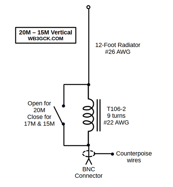
This is one of those antenna projects that started with: “I wonder if…” Designed with my Elecraft KH1 in mind, it covers the 20M, 17M, and 15M with the use of an tuner—similar to how the KH1’s whip antenna operates. It wasn’t something I had a burning need for, but it turned out to be pretty effective.
Concept
For many of my recent activations, I’ve been using my Elecraft KH1 with my base-loaded 12-foot whip. While I built the loading coil for 40M through 17M, I found that the KH1’s internal tuner easily matched the 12-foot whip on 17M and 15M, with the coil bypassed. A 12-foot radiator is resonant somewhere around 19.5 MHz, so it falls in between the 17M and 15M bands. Even though the 12-foot whip is a compromise, I was regularly making DX contacts on those two bands running five watts or less.
That got me thinking about building a more portable antenna for 20M through 15M using a 12-foot radiator. What I came up with was a simple 12-foot wire antenna that uses a loading coil for 20M and just the 12-foot wire for 17M and 15M.
When I thought about it, what I was building was conceptually similar to the Elecraft AX1 antenna and the KH1’s whip antenna. These antennas are close to resonance on 20M and resonant somewhere in between 17M and 15M. My antenna would operate the same way, except it would be almost 8 feet longer. I’ve always had good luck with the AX1 and the KH1’s whip antenna, so I figured my proposed antenna should work even better.
Along with the electrical properties, I wanted to make the antenna small and lightweight, using a #26 AWG radiator along with two 13-foot counterpoise wires. Also, I wanted to use—as much as possible—parts I already had in my junk box.
Parts List
I selected most of the parts based on availability in my junk box. They might not be the optimal choices, but here’s what I used:
T106-2 iron powder toroid
#22 AWG enameled wire (approx. 35 inches)
SPST slide switch. I actually adapted a DPDT slide switch, since I already had a bag of them.
#26 AWG wire (12 ft for radiator)
#26 AWG wire (2x13ft for counterpoise wires)
2mm banana plugs & jacks (2 sets for connecting the counterpoise wires)
(2) ring terminals
BNC female jack
(2) 4-40 x ¾-inch bolts plus some washers and nuts for the antenna and counterpoise connections. I used a couple of knurled nuts I had on hand.
Plastic box. I had one that measures about 2.5 x 1.75 x 1 inches.
Construction:
When I first thought about building this thing, I originally envisioned a more field-friendly form factor with built-in winders for the antenna and counterpoise wires. Since I constrained myself to using parts I already had (and I don’t own a 3-D printer), I used a plastic box I bought years ago but never used.
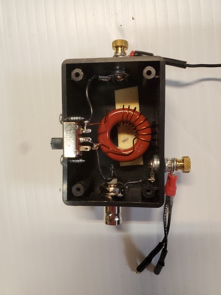
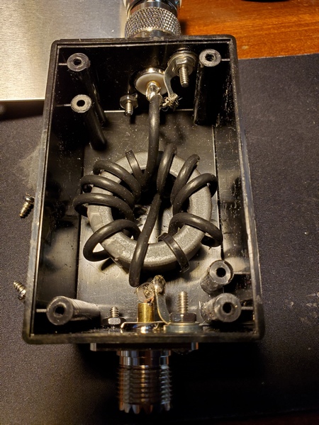
The construction was pretty simple; it’s just a toroid, a switch, and some connectors in a box. They say a picture is worth a thousand words, so have a look at the accompanying pictures to see how I built it.
Inside the matchbox
I used some online calculators to determine the loading inductance needed for 20M. Assuming I would need to tweak the number of turns, I started with one turn more than I had estimated. It’s easier to remove turns than to add turns—don’t ask me how I know this.
I used some foam mounting tape to hold the toroid in place. For good measure, I also wedged in a piece of Styrofoam between the toroid and the lid. That adds some assurance that the toroid won’t come loose in the field. The trickiest part was cutting a square opening for the slide switch. That took some careful work with a nibbler tool and a file to get it done without destroying the box.
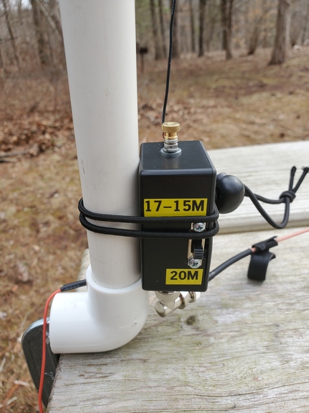
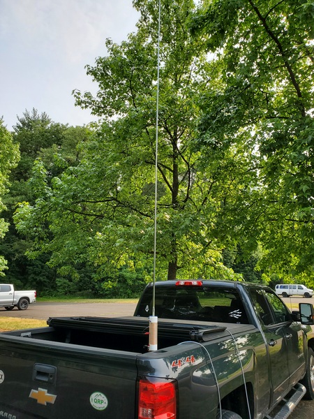
You could use a tree branch to support this antenna, but I like to keep my field setups self-contained. I found a cheap telescopic pole on eBay that measures about 12’ 3” fully extended, so I went with that.
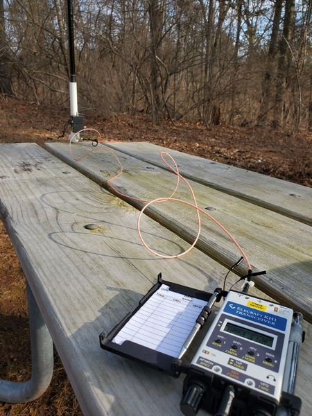
Typical picnic table setup with the 12-ft vertical and Elecraft KH1
I envisioned using this antenna primarily for “picnic table-portable” operation, running a short length of coax to the radio. Using a piece of PVC pipe and a PVC elbow fitting, I built a simple mount for clamping to a table. As luck would have it, the base of the pole fits perfectly inside a ¾-inch PVC pipe. I just use a C-clamp to fasten the elbow to the table and slide the pole into the pipe. When I built the mount, I inserted a small screw partway up the pipe to give the pole a few more inches of height. A six-foot length of RG316 is more than enough to reach the radio at the other end of the table.
Matchbox attached to the PVC pipe picnic table mount
Testing in the Field
I don’t have a good place for antenna experimentation where I live, so it took several trips to the field to tweak the inductor. On each trip, I took readings with an antenna analyzer, made any necessary adjustments to the loading coil when I got back home, and repeated the process on the next outing. That was a tedious process, which was spread out over a few months because of winter weather.
Once I set the antenna up in the field, I found I needed far fewer turns than I originally estimated. Initially, the antenna was resonating well below the 20M band, so I removed a turn at a time. Since I was going to need to use an ATU for 17M and 15M anyway, I didn’t get too fussy about getting it exactly resonant on 20M. However, I eventually got it resonating in the 20M band, with an SWR under 1.5:1 across the band.
The good news was that, even though I hadn’t finished tweaking the coil, the KH1 easily found a match. I had five successful activations during those testing sessions, typically running 3.5 to 4 watts. I consistently worked stations in Europe on all three bands, along with some U.S. stations on the west coast. On one outing, I worked W6LEN in California on all three bands from a park here in southeastern Pennsylvania. During my final testing session with the antenna, I had a 20-minute two-way QRP QSO with DL4ISX on 15M (CW). I declared the project completed at that point.
Below is a schematic showing the final configuration:
Wrap-up
So, there you have it. No revolutionary technical breakthrough here, just a fun little project that has been even more fun to use. I envision many more picnic-table-portable activations with it.
Back in 2017 I built my 19-foot wire vertical, which was my go-to portable antenna for about 4 or 5 years. The concept was simple: It functions as a base-loaded resonant vertical on 40M & 30M and as a random wire on 20M and up. The matching unit contains a tapped toroid for 40M & 30M and is fed through a built-in 1:1 choke. It occurred to me I could do something similar with the 12-foot telescopic whip and homebrew loading coil I’ve been using on my truck of late.
My 12-foot whip setup is resonant on 40M through 17M. You’re probably thinking: “Why not just bypass the loading coil and adjust the length of the whip for 15M through 10M?” Well, being as lazy as I am, that would make band changes a little more involved than I want to deal with. I like having some “frequency agility,” and I’m not above using an ATU to achieve that.
To emulate the scheme I used for the 19-foot vertical, I just needed a choke at the input to my homebrew loading coil. (I could probably go without the choke, but I wanted to keep the coax from becoming part of the antenna.) So, I use the 12-foot whip as a base-loaded resonant vertical on 40M through 17M. For 15M through 10M, I would bypass the coil and use an ATU.
To test this out, I threw together a choke using parts I had on hand. I wound 10 turns of RG-174 on an FT-140-43 toroid. A Radio Shack project box I had in my stash of parts was the perfect size to house the toroid. (I bought it a decade or two ago, and it was still unopened in the original Radio Shack packaging.) Since I installed SO-239 connectors on each end, I had to use an adapter to connect the choke to the SO-239 on the antenna. To hold the coil in place, I wedged a piece of foam packing material between the lid and the core. The completed choke is functional, albeit a little cheesy-looking.
The choke is 10 turns of RG-174 coax on an FT140-43 toroid.
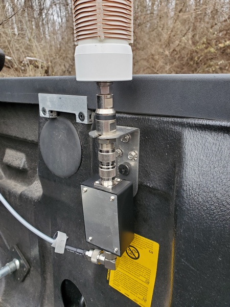
My first test using the 12-ft whip on the higher bands was a success. While activating Ridley Creek State Park (US-1414, KFF-1414), I used my KX3 (5 watts, CW) and installed the choke at the antenna feedpoint. On 40M through 17M, the loading coil functioned as it normally does. On 15M, 12M, and 10M, I bypassed the coil entirely and relied on the KX3’s internal ATU to load up the whip.
The choke installed at the antenna’s feedpoint
The KX3 easily found matches on all three bands, and my results on the air were encouraging. On 15M, I worked stations in Poland, Belgium, France, Ukraine, Germany (3), and the Slovak Republic. I made two stateside contacts on 12M. Up on 10M, I worked some more DX: Germany (2), Italy, and Czech Republic. One of the German contacts was park-to-park.
I’ve used this arrangement on a few more activations since then, including Winter Field Day. My results have been consistently good.
I haven’t done any modeling, but the 12-foot whip seems to be a pretty good length for operating like this. It’s just a little longer than a ¼-wave on 15M and a little shy of ⅜-wave on 10M. On 12M, it’s somewhere between ¼ and ½-wave; so it isn’t resonant on any of the bands of interest.
Although I was pleased with these initial results, I might do a little more tinkering with this setup. I’m toying with repackaging the choke to make it a little more weather resistant. I encountered some rain during the first activation using it. There was no damage to the choke at all, but I always have a tendency to over-engineer things—it keeps me occupied and out of trouble, I suppose.
No scientific breakthrough here. Just a lazy guy “force feeding” a fixed length whip to squeeze a few more bands out of it.
Reading through some blog posts recently, I came across an interesting idea from John AE5X. In the comments section of a recent post, John mentions adding a ground stud to a magnetic mount. The ground stud allows him to connect two ¼-wave radials (for 20M) for his MFJ-1979 telescopic vertical. So what follows is my implementation of John’s clever idea.
On occasion, I’ve used my Gabil GRA-7350TC vertical with a small magnetic mount salvaged from an old 2M/440 antenna. I plan to use this configuration on my (far) better half’s car while visiting family over the holidays. The mag mount is only 3.5 inches in diameter, so I’m sure it’s not providing much of a ground connection. While the Gabil vertical is certainly usable with this mount, I’ve always felt that it needed more of a counterpoise on 40M and 30M to obtain a better match. I figured John’s idea might be the way to go.
Since I needed to drill a hole from inside the mount, I had to remove the foil covering from the bottom of the mount. This magnetic mount is probably around 25 years old, so removing the foil wasn’t too difficult. Using my pocket knife, I was able to peel the foil off, while keeping it intact.
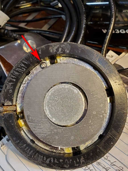
Next, I drilled a ⅛-inch hole through the ground plate and out through to the top of the mount. It was a tight squeeze, but I was able to get a 4-40 bolt and a star washer in there. On the outside of the mount, I used a nut and lock washer.
Interior view of the magnetic mount. It was a tight squeeze, but a 4-40 screw and star washer just fits in there.
The final step was to re-apply the foil covering on the bottom of the mount. I used some rubber cement to reattach it. I don’t know how well the rubber cement will hold up over time, but it won’t be seeing heavy use. It seems fine so far.
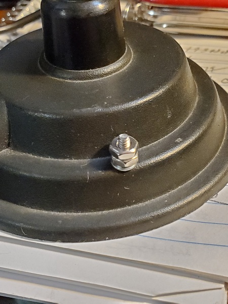
Exterior view of the old magnetic mount. I later removed the second nut from the screw I installed.
While I was at it, I replaced the PL-259 connector. The years had not been kind to the connector that was on there.
I gave the modified mag mount a try during a recent activation at US-1380, KFF-1380. I used the GRA-7350TC and mag mount on the roof of my truck. With no counterpoise wire attached, the best match I could get on 40M was just a hair under 3:1.
Next, I attached a 33-foot counterpoise wire to the mag mount. I ran the wire off the back of the truck and onto the ground. To avoid creating a trip hazard for others, I wrapped the wire around the side of the truck. In this configuration, I got the SWR down to about 1.2:1. Success!
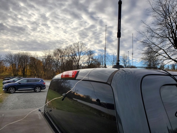
The Gabil GRA-7350TC and magnetic mount with one 33-foot counterpoise attached. The wire dropped to the ground behind the truck and wrapped around the side.
Using the same counterpoise, the best I could do on 30M was a little under 2:1. I tried two 16.5-foot wires, but the result was about the same. No worries. An SWR of 2:1 is a piece of cake for the Elecraft T1 tuner.
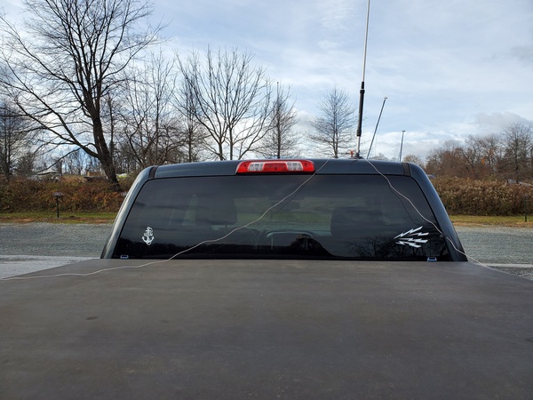
In this configuration, I had two 16.5-foot counterpoise wires attached.
I ran the entire activation on 40M and 30M with great results (40 contacts in less than an hour). In fact, it was the best I have done with the Gabil antenna and mag mount. Was it because of the counterpoise wire? Maybe. Regardless, my five-watt signal was getting out just fine with this thing.
It’s been a while since I’ve done a cheap speaker wire antenna, so here’s another one for you. Back in the early to mid-2000s, an antenna commonly referred to as the “No Counterpoise Antenna” was making the rounds on the Internet. I thought I might give it another look.
The No Counterpoise Antenna is either a 25-foot or 50-foot length of two conductor wire with half of one conductor removed. Essentially, it’s a radiator fed through a balanced line feeder. The 25-foot version is said to cover 20M through 10M, while the 50-foot version is supposed to cover 40M through 10M. It was usually connected to a balanced tuner of some sort or sometimes fed through a 4:1 balun. It was typically constructed from zip cord or speaker wire. So, this is perfect for another speaker wire project. (Actually, I built the 50-foot version years ago, but I don’t recall ever putting it on the air.)
A picture is worth a thousand words, so here goes:
I’ve seen this antenna sometimes referred to as a Zepp. A true Zepp is basically a half wave radiator with a quarter wave balanced line matching section. Unlike a true Zepp, the No Counterpoise Antenna is non-resonant, so I guess it’s actually “Zepp-ish.” Because it’s non-resonant, a tuner is required for this antenna.
I did some extensive research into the origins of this antenna. (OK… I just did a few Google searches.) Jeff Imel K9ESE came up with this design. I remember Jeff used to sell a high-quality version of the antenna on eBay. The reviews were generally positive.
Pete Millis, M3KXZ, is another name often associated with this antenna. I think that’s how I first came across it. Pete once made a phased array from two 25-foot versions.
In the August 2020 edition of Ozark QRP Banner, the Four State QRP Group’s newsletter, Terry Fletcher, WAØITP, had a nice write-up about it. He discusses his experience with both the 25- and 50-foot versions.
This antenna design has been around the block a time or two. So, there’s no innovation here on my part whatsoever.
Construction
I happened to have a 25-foot roll of #18 awg speaker wire on hand, so this time around, I opted to build…you guessed it… the 25-foot version.
Construction was about as easy as it gets:
I split the speaker wire halfway and cut off one side
Next, I twisted a loop at the end of the single wire and secured it with some Goop® adhesive. As an alternative, you could just tie a loop at the top or crimp a ring lug over the wire’s insulation.
I stripped and tinned the wires at the feedpoint and installed spade lugs. You can just strip and tin the wires, if you like.
To keep the speaker wire from splitting further, I put some heat shrink tubing a couple of inches up from the lugs. I also added a dab of Goop® in the middle of the antenna where one side of the wire was removed. All of this is completely optional.
Construction probably took me all of 15 minutes or so. That doesn’t include allowing the adhesive to cure overnight. However, the antenna was certainly usable without the adhesive and heat-shrink tubing I used. I’m just prone to overkill.
On the Air
To test the No Counterpoise Antenna, I drove down to Ridley Creek State Park (US-1414, KFF-1414). Using my drive-on mount, I supported the antenna from a 28-ft Jackite pole. I used a homebrew 4:1 unun at the feedpoint and ran 15 feet of coax into the cab of my truck to my KX3 (5 watts, CW). I used the long side of the antenna as the radiator.
I used my roll-on mount to support a 28-ft Jackite pole
Before I got started, I checked to see how the tuner in the KX3 would handle the antenna. The KX3 easily found a 1:1 match on all bands from 40M through 10M. Just for the heck of it, I tried 60M and 80M. The KX3 was able to find a good match on those bands, too. (That’s not too surprising, given that I once forgot to attach my coax to an antenna, and the KX3 still found a match.) I doubt this antenna would work well on 60M and 80M—but stranger things have happened. I wasn’t able to try it, but I’m sure the KX3 would be able to match it directly connected to the radio without the 4:1 and coax.
I used a 4:1 unun at the feedpoint
Band conditions weren’t very good, so this wasn’t an ideal test. Despite the mediocre band conditions, I logged 13 contacts during my short activation. Most of my contacts were on 40M. There was considerable fading on 30M and 20M, but I made a contact on each of those bands.
This was hardly a rigorous evaluation, but the 25-foot No Counterpoise Antenna got the job done. I need to give it another try, when conditions are better.
Anyway, if you have some speaker wire and a few minutes to spare, give this one a try and see what you think.
Back in December, Becky Schoenfeld W1BXY, Editorial Director for ARRL’s On the Air magazine, asked me if I would be interested in writing a detailed set of step-by-step instructions for my Drive-on Portable Antenna Support. Naturally, I said I would.
I submitted my manuscript, along with an all-new set of pictures. The article was published in the current issue (May/June 2024) of On the Air (pages 20-22).
If you’re interested, have a look. ARRL members have access On the Air as part of their membership.
Whenever I buy parts for a project, I always buy one or two extras. Over the years, I’ve amassed a sizable collection of random parts. Some of it will never be used, but sometimes my collection of parts has just what I need for something I want to build. I like when that happens.
A while back I wrote about an old homebrew coil I resurrected and paired with a 12-foot telescopic antenna. The coil, while effective, was built to use with a much shorter whip and is larger than what I need. I scoured my junk box and came up with most of the parts I needed to build a scaled-down version.
I should note that I built this coil specifically to use with my old MFJ-1956 12-foot telescopic whip. In this configuration, this coil covers 40M through 17M. So, if you have a different whip or want to cover different bands, you’ll need to modify the design accordingly.
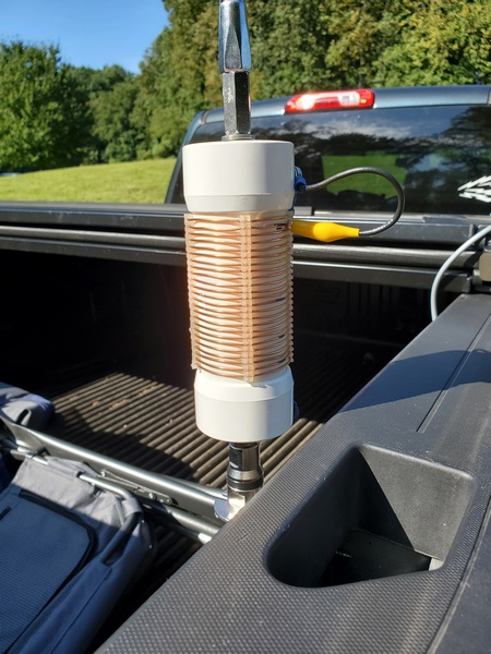
Completed loading coil. Used with a 12-foot telescopic whip, it tunes from 40M through 17M.
I used the old coil as a guide to determine the number of turns I needed to cover the bands of interest, adding two turns for good measure. Using an online shortened vertical calculator, I figured I would need about 13.4μH to load the 12-foot whip on the 40M band. Using an online coil inductance calculator, I estimated the total inductance of my coil to be 14.8μH. So, it covers 40M with a turn or two to spare.
The new coil assembly measures 8.25 inches end-to-end, making it 2.25 inches shorter than the old coil. While it’s about 3.3 ounces lighter than the old coil, this new coil still weighs in at a hefty 10.8 ounces.
Parts List
With a few exceptions, my junk box provided the parts I needed to build the coil.
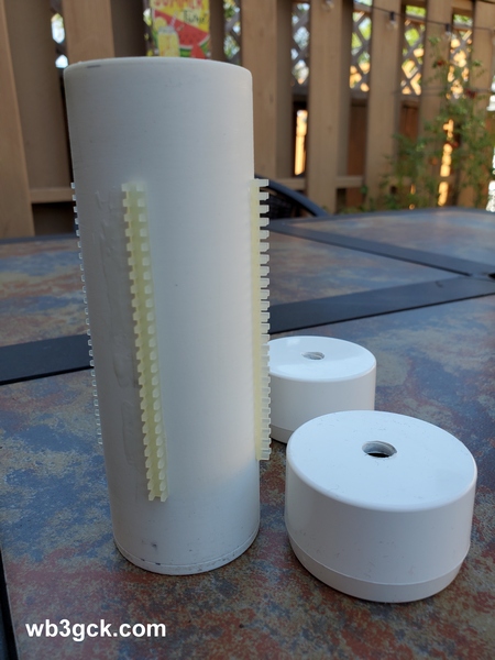
5-3/8 inches of 1.5 inch PVC pipe
(2) PVC end caps for 1.5 inch PVC pipe
(4) pieces of nylon grommet edging, 3.25 inches each. (The material I used has about 8 notches per inch)
16 gauge bare copper wire, approx. 12.5 feet
(1) 3/8-24 coupling nut, 1-1/8 inches long
(1) 3/8-24 x 1-1/4 inch stainless steel bolt (bottom mounting stud)
(1) 3/8-24 x 1 inch stainless steel bolt (top bolt)
3/8 inch flat washers & lock washers
(2) #10 x 3/4-inch self-tapping screws
Approx. 6 inches of RG-174 coax
Small alligator clip
Misc: ring lugs for ⅜-inch & #10 screws
Construction Notes
As shown in the accompanying photo, I drilled the end caps to accommodate the ⅜-24 bolts. The 1-1/4 inch bolt was used for the bottom of the coil, along with a flat washer and a lock washer. The 1-inch bolt was used for the top, along with flat washer, lock washer, and the coupling nut.
This is the coil form with the four strips of grommet edging glued on. The ends were drilled to accommodate the 3/8-24 bolts.
The coupling nut was one item I didn’t have in my junk box. My local hardware store is well-stocked, but they didn’t have them with the ⅜-24 thread. I eventually found what I needed on Amazon. It was a little pricey, but I didn’t have any better options at the time.
After cutting the PVC pipe to length, I temporarily installed the end caps. Then, I cut four pieces of the grommet edging to length and glued them on, using Goop® adhesive. Unfortunately, I can’t provide a part number and source for the edging. A local QRPer, Ron Polityka WB3AAL (SK), gave me several pieces many years ago. I’m pretty sure Panduit was the manufacturer. My stash was nearly depleted, but I had enough left for this project.
Before assembling the end caps, I made two short jumpers, each with a ⅜-inch ring lug on one end, and a smaller ring lug on the other. Then I tightened everything up. I left about a ½ inch of thread on the top bolt to go into the coupling nut. I was careful to ensure that my whip antenna would fully thread into the coupling nut.
Before winding the bare wire on the coil form, I installed a ring lug on one end. I drilled a pilot hole in the side of the lower end cap and used a self-tapping screw as a connection point. When you wind the wire on the coil form, try to get the turns as tight as you can. (I didn’t do as good a job winding the coil as I would have liked.) Once I finished winding the coil, I cut the wire to length and installed a ring lug. I used some more Goop adhesive on the grommet edging to hold the turns in place.
The last step was to build the clip lead. For this, I used a piece of RG-174 coax. There’s nothing magical about the RG-174; stranded hookup wire would be fine. I used RG-174 primarily because of its flexibility, plus the shield would be a good RF conductor. (The center conductor was unused.) I crimped and soldered a ring lug to the braid on one end, and soldered an alligator clip to the braid on the other end. Then I used another self-tapping screw on the top end cap to connect everything together.
On the Air
I wrote about my initial tests of the coil in a previous post. Using an antenna analyzer, I determined where to place the tap for each of the four bands. I then used a permanent marker to mark these locations on the coil, so I can quickly change bands without resorting to the antenna analyzer.
This is the completed loading coil installed on my truck for a POTA activation.
With the antenna mounted on my truck, the SWR is higher than I would like on 40M and 30M. This is not unlike other shortened, base-loaded verticals I’ve used in this configuration. An additional counterpoise wire or two might help. Also, grounding the bottom of the coil and feeding it a couple turns up from the bottom would provide a precise match on the lower bands. I’ve used that technique in the past. That configuration , however, is a bit more complicated to implement, given the way I plan to use this coil. So, I just use a tuner to keep the radio happy, and the antenna seems to work fine.
Wrap-up
My older, larger coil worked fine; so technically, this project was unnecessary. But, since I had most of the parts on hand, what the heck. It was a fun project, and I’m sure it will see a lot of use in the future.
In a recent post, I wrote about a vertical antenna I put together with an old homebrew loading coil and a 12-foot telescopic whip. I intended to add some marks on the coil for each band, so I could eliminate the need for an antenna analyzer during band changes. This time, I actually remembered to bring a permanent marker and got it done.
I drove up to Evansburg State Park (K-1351/KFF-1351) this morning for a quick POTA activation. Before I got going, I used my antenna analyzer to determine the tap points for each band. I used a Sharpie® marker to mark the coil for 40M, 30M, 20M, and 17M. Since the coil has sufficient inductance to load the 12-foot whip on 60M, I also marked that band (the top-most mark on the coil). Before I started operating, I went back and checked each tap location to confirm repeatable results. Using a Sharpie marker is a decidedly low-tech approach, but it serves the purpose.
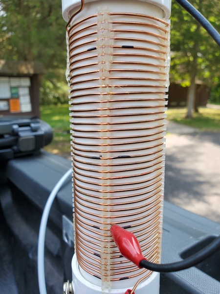
My homebrew loading coil. If you look closely, you can see the marks I added. As shown, the coil is tapped for the 30M band.
To change bands now, I just move the tap to the appropriate mark. I still use an antenna tuner to deal with any minor variations I might encounter. Now I can change bands in the time it takes to move the coil tap and hit the “tune” button on the tuner.
Despite the so-so band conditions this morning, the 12-foot whip performed well. In less than an hour of operating, I made 18 contacts. Most of my contacts were on 40 and 30. There were two park-to-park contacts I’m aware of.
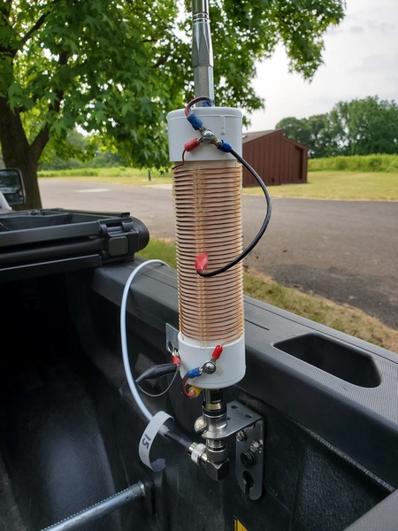
The 12-foot base-loaded whip in use at K-1351
My operations were interrupted for a chat with a curious park ranger. I gave him my standard Parks on the Air spiel. He had encountered POTA activators in another state park, so he had some familiarity with the activity. After a few minutes, he left to look into a reported issue on one of the hiking trails.
So, I’m pretty satisfied with this antenna. It has a length advantage over my Gabil GRA-7350TC antenna. Comparing coil dimensions, I suspect it also has an efficiency advantage over the Gabil antenna.
Regardless, I now have another useful option in my antenna arsenal.
While going through my stash of old parts, I came across a coil assembly I built over 20 years ago. Originally, it was part of a homebrew antenna inspired by the MFJ-1622 Apartment Antenna; but I used it over the years with a variety of whip antennas while “stationary-mobile.” As I moved on to other antennas for my portable operations, the coil was relegated to the junk box and forgotten—until now.
I also had an old MFJ-1956 12-foot telescopic whip that I haven’t used in years. It was stashed away in the basement waiting to become part of a new antenna project. Having just installed a ⅜-24 antenna mount in the bed of my pickup truck, I thought the coil and whip might work well with it.
The coil is a beast. It’s made from 1.5-inch PVC pipes and wound with bare copper wire—16 awg, I think. I used four strips of nylon grommet edging material to keep the turns evenly spaced. (I don’t remember where I got the grommet material, but it’s similar to this Panduit product.) The coil is about 5.4 inches long and 2 inches in diameter with 40 turns. Using an online calculator, I figured the coil is approximately 25.4 μH.
The homebrew coil I built more than 20 years ago.
The coil assembly weighs in at a hefty 14.1 ounces, and the overall length is 10.5 inches. The whip is 24 inches collapsed and weighs 9.6 ounces, so it wouldn’t be my choice for a backpacking antenna. However, on my truck, it should do fine.
Using another online calculator, I reckoned the coil should be more than enough to resonate the 12-foot whip on the 40M band and possibly the 60M band. Since the whip, coil, and mounting bracket all use ⅜-24 hardware; it was just a matter of slapping it all on the truck to see what how it would perform.
To test it out, I made a trip to Valley Forge National Historical Park (K-0761, KFF-0761) this morning. With a minor geomagnetic storm underway, the forecasted band conditions looked pretty dismal. I also got an early start, since we were expecting some severe storms around mid-day. So, I wasn’t expecting much, in the way of contacts.
I mounted the antenna on the back of the truck and broke out the antenna analyzer. It took a bit of fiddling to find resonance on 40M. The lowest SWR was around 3.8:1. That’s not great, but my little Elecraft T1 tuner handled it with no difficulties. On the air, I was getting some decent spots from the Reverse Beacon Network, and I made about 8 contacts before moving to 30M.
My homebrew coil and 12-foot whip mounted on the back of my truck.
The SWR on 30M was down to about 2:1. Again, the T1 made sure my TR-35’s finals stayed happy. I made one park-to-park contact on 30M before moving up to 20M
The SWR on 20M was about 1.3:1 across the band. I made another seven contacts here, before stopping to do some experimenting with the antenna.
I checked 17M and measured an SWR of about 1.2:1 across the band. I didn’t try to make contacts on 17M. Instead, I went back to 40M to pick up a few more contacts before shutting down.
I intended to bring a Sharpie® pen along to mark the coil for each band to speed up band changes. Of course, I forgot to bring one along. Oh well, I’ll do that next time. For 15M and above, I’ll need to bypass the entire coil and shorten the length of the whip accordingly.
The static crashes were getting louder, and I heard thunder off in the distance. So, I called it quits. Just as I shut the rig off, the heavy rains started. I quickly took down the antenna and packed up to leave.
Despite the lousy band conditions and heavy QRN, I ended up with 18 contacts. I had three park-to-park contacts today. And, as it turns out, this was my 20th POTA activation at Valley Forge, earning me a “Repeat Offender” award for this park.
It looks like this mash-up of antenna parts works pretty well. I’ll give it another shot in a few days. Hopefully, the weather and band conditions will be better.
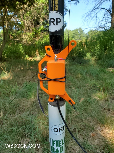
I recently came across a product on Etsy that caught my eye. It’s a 3D printed project box with an integrated antenna wire winder. I couldn’t resist, so I ordered one.
The box will accommodate a T-130 toroid, and the snap-on lid comes with a gasket. There is a pre-drilled hole for a BNC-F panel mount connector, and there are marks to guide drilling for the output and ground connectors of your choice. You can choose from two colors: orange or green. The vendor states that it is “UV and weather resistant.”
I like the idea of having a box to enclose the balun or transformer. My preference for portable antennas is to avoid exposed components or circuit boards.
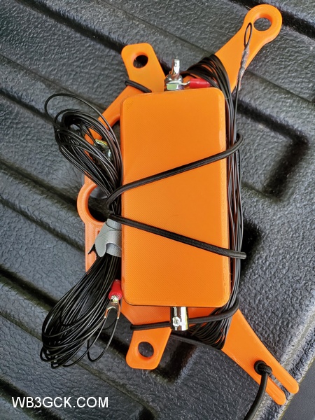
I used mine to build a 4:1 unun for portable use in a Rybakov configuration. The unun consists of 19 bifilar turns of #24 solid hookup wire on a T130-2 toroid. You can find plans for winding the unun here and other places on the Internet. For the output and ground connections, I used #10-24×3/4″ stainless steel machine screws, along with some nuts, flat washers, and lock washers.
Inside view of the 4:1 unun. I used double-sided foam mounting tape to secure the toroid. I also use a small piece of packing foam (not shown) between the lid and the toroid for added stability.
To go along with the completed unun, I prepared two 26-foot wires; one for the radiator and one for a counterpoise. I finished up by attaching a length of 2.5mm bungee cord. This cord keeps everything together for travel. I have also used it to secure the box to a vertical support, e.g., fiberglass mast, fence post, etc.
The 4:1 unun deployed in a Rybakov vertical configuration with a 26-foot radiator and a 26-foot counterpoise
In the field, this Rybakov antenna worked as well as others I have built over the years. I tested it using my Penntek TR-35 and Elecraft T1 tuner with 18 feet of coax. It tuned up easily on 40, 30, 20, and 17 meters, and I made a couple of QSOs while testing. The integrated winder made it easy to deploy and take down.
The 4:1 unun packed up for travel
I have a feeling another one of these boxes is in my future. Maybe a 9:1 unun next time?