A while back I purchased one of AD8HK’s end-fed random wire (EFRW) antennas. I tried it for the first time during my ill-fated Flight of the Bumblebees (FOBB) outing. With everything that went wrong that day, the AD8HK antenna certainly deserved a better evaluation—at least one where I wasn’t in a panic over problems with my newly acquired Elecraft KH1.
The AD8HK EFRW is a really slick little antenna. It consists of a 15-foot radiator and a 7.5-foot counterpoise wire. It has a neat 3-D printed winder for the wires that also incorporates a 4:1 unun and BNC connector. It’s compact and well-built. AD8HK Antenna Systems sells this antenna (and other offerings) through eBay.
During my infamous FOBB outing, I fed the antenna with 6 feet of RG-316 coax. It loaded up on 30M through 15M, but neither my KH1 nor my Elecraft T1 tuner could find a match on 40M. I’m not sure what the issue was, but I didn’t have much time to look into it.
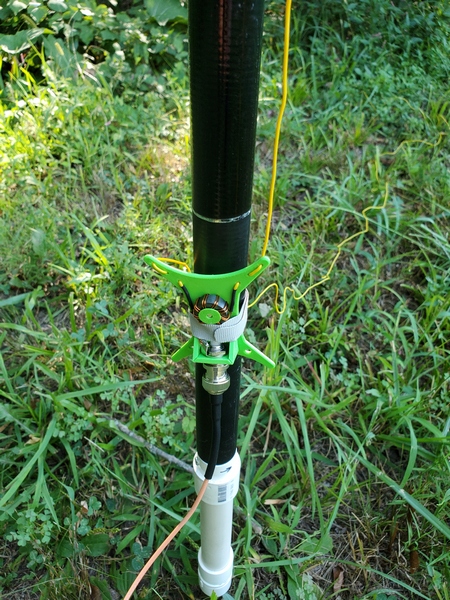
The AD8HK winder/unun secured to the pole with a Velcro strap.
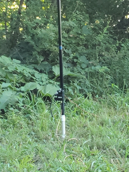
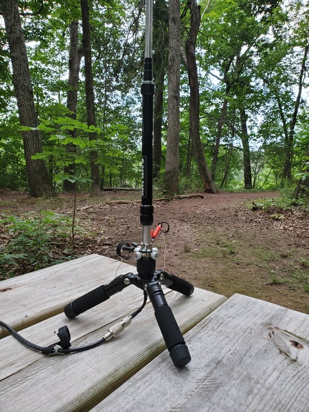
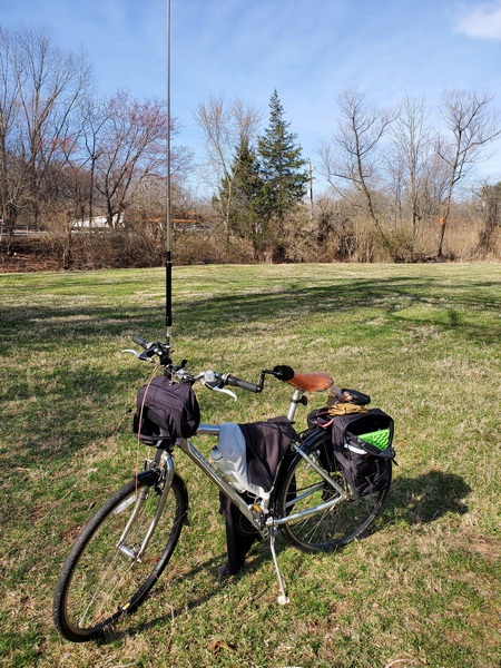
This morning I took the AD8HK EFRW over to Valley Forge National Historical Park (US-0761, KFF-0761) for an activation. I supported the antenna with a 20-foot pole and my homebrew ground mount. I fed the antenna with 20 feet of RG-316, and this time my T1 ATU easily found a match on 40M. It also loaded up fine on 30M through 17M.
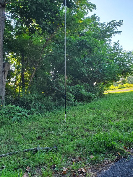
My antenna pole
A 15-foot radiator isn’t going to be a barn burner on 40M; however, this little antenna certainly held its own today. I easily logged 13 contacts on 40M before moving on to try other bands. When I wrapped up after a little over an hour, I had twenty contacts in the log, with four park-to-park contacts. I made contacts on all four bands covered by my Penntek TR-35 (40M-17M), and I was pleased to work W6LEN out in California on 20M.
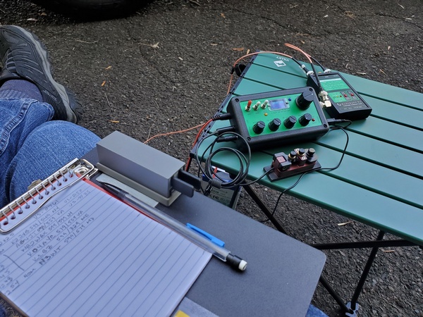
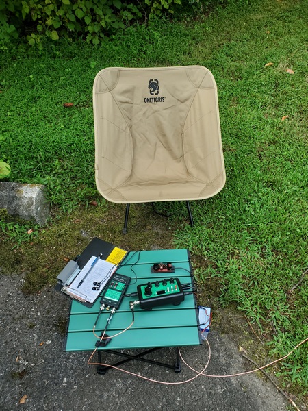
My usual set up: Penntek TR-35 and Elecraft T1 ATU
After today, the AD8HK EFRW has definitely earned a spot in the KH1 kit I’m putting together. It’s easy to deploy and has a relatively small footprint.
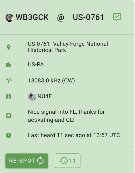
Thanks to NU4F for the nice spot from Florida
Speaking of my KH1… I heard from Elecraft a few days ago. They replaced the FET in the final amplifier, and now the rig is on its way home. I can’t wait to get it back on the air.
Once again, the NJQRP Skeeter Hunt contest coincided with our annual family vacation to the Outer Banks of North Carolina. I’m certainly not a hardcore contester, but I wanted to set aside some time to make a few contacts from North Carolina. Although our rental house was beautiful, it presented some challenges for ham radio.
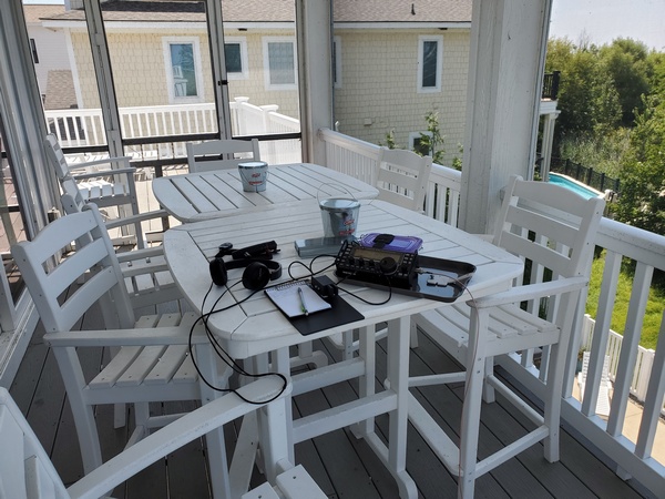
Operating in the NJQRP Skeeter Hunt contest
After a long drive down and all the unloading/unpacking the day before, I didn’t feel like getting too crazy putting up an antenna. Although this was our first time in this rental house, I had a good feel for the layout from online research.
My “shack” for the week
My previous experience has shown that these rental properties come with a lot of RF noise, both from within the house and from neighboring houses. The house this year was no exception. So, I stayed away from vertical antennas near the house and went with an end-fed random wire sloper.
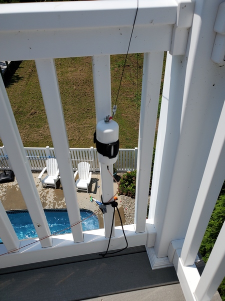
The antenna this year was a 35-foot wire, sloping down from the 3rd-story deck. I fed it through my homebrew weather-resistant 9:1 unun and ran 25 feet of coax into a screened-in porch on the same level. I attached the end of the wire to a fence around the pool area, making sure it wouldn’t get in anyone’s way. The wire was a bit long, so I ran the last two feet horizontally along the top of the fence.
My antenna feedpoint. The far end of my random wire sloped down to the fence by the pool.
I fired up my KX3 and checked the bands. A quick contact with a POTA activator on 40M confirmed it was putting out some sort of signal. The noise on 40M, however, was horrendous in places. The higher bands were better but still somewhat noisy. I hunted four POTA activators while experimenting with the antenna. Two of the contacts were easy, while the other two were tough going.
I also had to contend with some audio interference from my grandkids having fun in the pool down below. Anticipating this, I brought along a pair of over-the-ear headphones this year. Unfortunately, the headphones were no match for four exuberant kids.
Once the contest started, the noise level on 40M was about S3 in parts of the band, and S5-S7 in other parts. There was also a loud noise signal that would slowly sweep across the band from time to time. Despite the noise, I worked four skeeters and one very confused QRO station who wasn’t in the contest. He probably thought I was a POTA activator and couldn’t figure out why I needed to know his power output.
Up on 20M, the noise was lower but still present. I didn’t hear much Skeeter Hunt activity, despite getting some respectable hits on the Reverse Beacon Network. I ended up with a pair of Missouri skeeters in the log. I tried calling CQ on 15M with no luck.
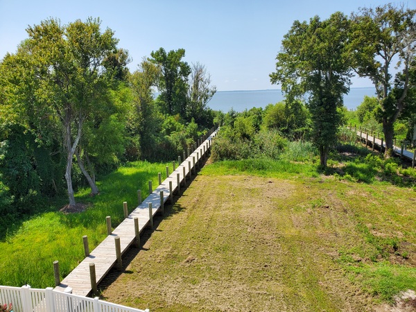
After a little over an hour, I threw in the towel. My operating position was facing west across Currituck Sound, so my nice shady spot was giving way to the afternoon sun. Before I pulled the plug, I had one last contact on 40M with a friend back in Pennsylvania.
The view from the antenna
So, my 2025 Skeeter Hunt results were less than stellar. Although it was frustrating working through the noise, I still had fun. Plus, the scenery from my temporary “shack” was outstanding.
In my last post, I talked about using a simple antenna comprising a 15-foot radiator, a 7.5-foot counterpoise, and a 4:1 unun. It worked well, but I found it a little touchy to tune on 40M. Today, I tried the same configuration, but with a slightly longer radiator and counterpoise.
I wanted to add a little length to the radiator, but limit it to 19 feet, so I could still use my lightweight 19.5-foot telescoping pole to support it. Looking at a table of random wire antenna lengths to avoid, it seemed like 18 feet might be a good choice for 40M through 15M, my primary bands of interest. Scaling the counterpoise wire proportionately, I went with a length of 9 feet.
Just as I was getting ready to cut a set of wires to try out, I stumbled on a video by Thomas K4SWL. In the video, he was using an antenna built by AD8HK that used a radiator length of 17’9” and a counterpoise length of 8’10.5”. I went with those dimensions, since they were very close to what I was considering and seemed to work with Thomas’s KH1.
On the Air
To try it out, I made a quick trip over to Valley Forge National Historical Park (US-0761, KFF-0761). Using the same 4:1 unun and coax as the last time, I made a quick check to see how my Elecraft T1 loaded up on the bands. The tuner quickly found a match on 40M, 30M, 20M. On 17M, however, it seemed to struggle. I went back to 40M and got started with my activation.
This wasn’t the best day to be doing this. The geomagnetic field was unsettled with a K index of 4 and the A index sitting at 47. Nevertheless, the callers showed up, although at a somewhat slower pace than usual.
After I had 14 contacts in the log, I decided to spend the rest of my limited time playing around with the antenna. When I went back and checked 17M, the T1 tuned it up without flinching. I also rearranged the counterpoise wire so it ran 180 degrees opposite of my coax. Checking the bands again, the T1 reliably matched 40M through 17M.
Convinced that the new wire lengths work, I went back to the 15-foot radiator and 7.5-foot counterpoise I used a few days earlier. This time, the T1 had no issues loading up on 40M. Go figure!
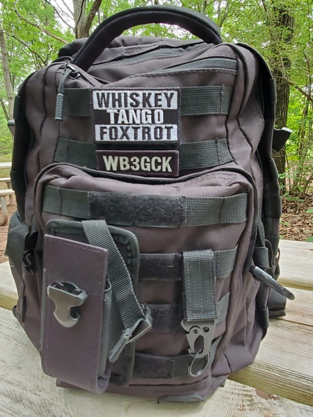
I really wanted to give the unun with the smaller ferrite core another shot. When I last tried it with the 15-foot & 7.5-foot wires, neither my KH1 nor my T1 could find a match on 40M. Unfortunately, I neglected to put it in my backpack before I left. I’ll have to save that for another time.
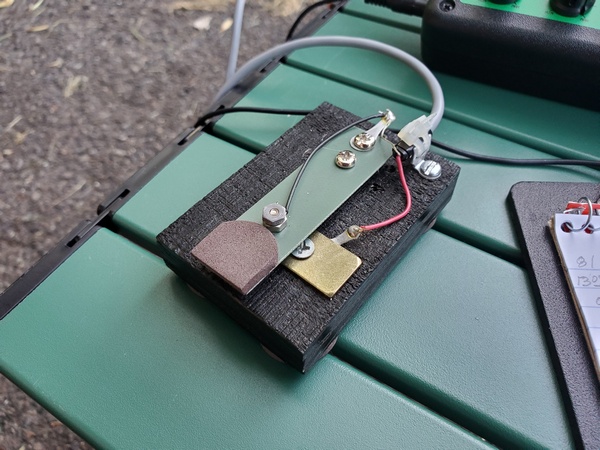
The Straight Key Century Club (SKCC) Weekend Sprintathon contest was going on this weekend, and I worked one SKCC station while tuning around the bands. This month, the WES theme was homebrew keys. In the spirit of the contest, I made the contact using a straight key I built a few years ago from junk box parts.
My homebrew straight key constructed from odds and ends from my junk box
Conclusions
So it looks like both the 15’/7.5’ and 17’9”/8’10.5” configurations are usable with my homebrew 4:1 unun. Given a choice, though, I would probably stick with the longer wires.
One other thing is clear: short random wires can sometimes be finicky little critters. When in doubt, rearrange the counterpoise wire.
On Wednesday, August 7th, I set out to do some antenna experimentation. So, why not get in a POTA/WWFF activation at the same time? To kill those two birds with one stone, I drove down to Ridley Creek State Park (US-1414, KFF-1414). (Disclaimer: No birds were actually harmed during this activation.)
I saw some discussion on the Internet about an antenna configuration I found intriguing. It’s just a 15-foot radiator and a 7.5-foot counterpoise wire fed through a 4:1 unun. Folks claim they work on 40M through 15M—with a tuner, of course. I’m a sucker for simple, field-expedient antennas, so I gave it a try during the recent Flight of the Bumblebees contest.
With the unun I used, I had mixed results. I couldn’t get the antenna to load on 40M, but it seemed to do fine on 30M through 15M. I wanted to try the same configuration, but with a larger 4:1 unun I built a several years ago. After cutting another set of 15-foot and 7.5-foot wires, I was ready to go.
My antenna feedpoint
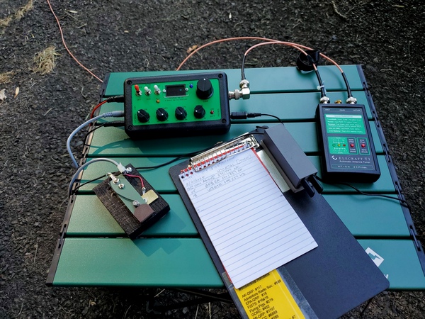
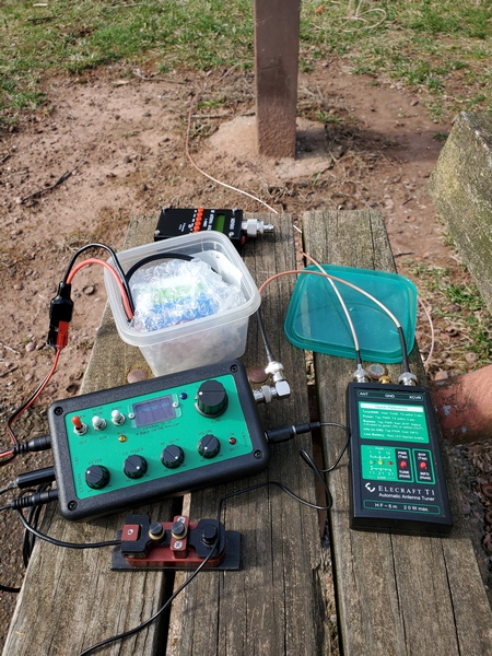
When I got to the park, I headed to a spot I had been using a lot lately. It’s off the beaten path and well away from the other park visitors. Using my homebrew ground mount, I set up the antenna on a lightweight 19-ft telescoping pole I bought years ago on eBay. I ran 20 feet of RG-316 coax over to my Penntek TR-35 and Elecraft T1 tuner.
My operating position
Before I started my activation, I gave the antenna a quick check. The antenna was an easy match on 30M through 17M, but it took two tries before the T1 found a good match on 40M.
Despite the slightly fussy tuning on 40M, the antenna didn’t do too badly on that band. I logged 12 contacts before the activity slowed down. I next tried 30M, but there were no takers. Moving up to 20M, I logged three more stations. Up on 17M, I worked one last station in Alabama. After an hour on the air, I had 16 stations in the log, including five park-to-park contacts.
Something in the woods behind me was not happy with my presence. Fortunately, I never came face-to-face with whatever it was.
I had better luck with this antenna configuration this time around. The unun I used for this outing uses a larger iron powder toroid (T130-2, as I recall) compared to the smaller ferrite core used in the other unun. Also, the longer run of coax I used this time was probably a contributing factor.
In any event, this configuration can definitely work. Granted, it’s a compromise antenna, but it’s super simple to deploy for casual operating in the field. Still, I think a slightly longer radiator would make for an easier match on 40M.
I have another configuration in mind that I plan to try soon.
Actually, this bumblebee barely got off the ground at all this year. It started off with a heartbreaking rig failure and ended with some horrendous local noise.
I had a late-breaking change of plans this week. I originally planned to operate in the Flight of the Bumblebees (FOBB) contest from a nearby POTA entity. Instead, I ended up in central Pennsylvania helping a family member recovering from a recent surgery.
So, I activated Plan B: take my new KH1 along and make a few contacts from the backyard. What could go wrong with that? A lot, as it turns out.
Using my homebrew ground mount, I set up a new antenna on my lightweight telescopic pole. The antenna comprises a 15-foot radiator and a 7.5-ft counterpoise fed through a 4:1 unun. (More about that antenna in another post.) I ran a 6-foot length of RG-316 coax over to the KH1.
I easily got a 1:1 match on 20M and up, but it wouldn’t load up at all on 40M. Going back to 20M, I started operating. Something on the display didn’t look right. It turned out that I wasn’t getting any power output. When I pressed the ATU button, I heard some relay clicking, but there was no power or SWR displayed after tuning. When I keyed up, the display showed zero bars of power and one bar for SWR.
I checked to make sure I wasn’t in “Test” mode (I wasn’t). Next, I started pouring through the settings to make sure I hadn’t messed something up. Nothing looked out of the ordinary to me. I tried the built-in whip on 20M, but still no power out.
After spending an inordinate amount of time playing around with the KH1, I packed it up and brought out my Penntek TR-35. My trusty Elecraft T1 ATU also refused to load up on 40M.
So, 20M was the only band working for me, given the rig I was using. I could have set up a different antenna, but I didn’t have that much time.
The 20M band had some horrendous local noise, so it was rough going. I worked one bumblebee in Missouri, and that was it. Frustrated with my inability to hear any other FOBB activity through the noise, I called it quits. I needed to get back inside to take care of a few things, anyway.
Having owned my KH1 for less than a week, you can imagine my disappointment. I shot off a message to the support folks at Elecraft, so hopefully, they can help get this issue resolved before I head down to North Carolina on vacation next month. (Fingers crossed)
Wanting to take advantage of the excellent weather today, I drove up to Evansburg State Park (US-1351, KFF-1351) for a quick morning activation. I wanted to give my Gabil GRA-7350TC vertical some air time, so I tossed it into the truck and headed out to the park.
The picnic table I planned to use had been moved from its usual spot. Not wanting to drag the heavy table back to where it belongs, I set up at a table I have used previously. It’s close to a hiking trail, so I needed to make sure my radials wouldn’t be a trip hazard for passersby.
I set up the Gabil antenna on its tripod at one end of the table. To facilitate tuning, I set up my Penntek TR-35 (5 watts, CW) and Elecraft T1 ATU within arm’s reach of the antenna. I meant to bring a 3-foot coax along, but it didn’t make it into my backpack. A 10-foot cable was the best I could do, so I just coiled up the excess. (Note to self: Keep a 3-foot cable in the backpack.)
I started out on 40M, so I laid out a 33-foot counterpoise wire on the ground. I reached for my little SWR meter, but it wouldn’t power on. It had been a while since I had last charged it, so the battery appeared to be dead. I ended up adjusting the antenna for maximum noise in the receiver and used the T1 to do the final matching.
After I had a few contacts in the log, I changed over to 20M. I built my 33-foot counterpoise wire so I could split it into two 16.5-foot wires. After laying out the two counterpoise wires, I tried to peak the noise. No joy. I just couldn’t find a discernible peak.
Just then, I remembered I had a 12-volt power cable for the SWR meter. Duh! Why didn’t I think of that sooner? After temporarily disconnecting the TR-35, I used the battery to power the SWR meter. I quickly got the antenna adjusted to a 1.3:1 SWR. I reconnected the TR-35 and got started. (Note to self: Throw a Powerpole splitter in the backpack.)
The action was relatively slow-going this morning, but there were a fair number of activators on the air. After a little over an hour, I had 14 contacts, nine of which were park-to-park.
Despite some minor glitches, it was an enjoyable morning operating in the park.
It has been quite a while since I’ve done any bike-portable operating. Over the past couple of years, I’ve dealt with medical issues of one sort or another. This year, I’ve avoided any serious issues, so I dusted off the bike and went out for a ride. While I was out, I tested some new gear for the bike. (I purchased all of the products mentioned with my own money.)
Antenna Mount
I make no claims of originality for this setup. I first saw this antenna mount in a YouTube video by VA7BIX. So, I found one on eBay and fired off an order to give it a try.
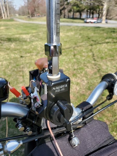
The antenna mount in question is a Nagoya RB-46. I had been looking for a way to mount my Gabil GRA-7350TC antenna (or any antenna with a ⅜-24 mount) on my bike. Originally intended for mounting on a car’s roof rack, the RB-46 can be clamped to the handlebars on bikes. With the kickstand down, my bike leans a bit. Fortunately, I can the adjust the RB-46 in two directions, so the antenna stays vertical. It accommodates a standard SO-239 to ⅜-24 antenna stud mount, which I had on hand.
Installing the RB-46 is quick and easy—for normal people. My installation, however, required extra time for searching the garage floor for dropped nuts and washers. Hardware mishandling aside, I installed the mount on my handlebars and adjusted it so the antenna would be vertical with the bike’s kickstand down.
Nagoya RB-46 antenna mount attached to my handlebars with my Gabil GRA-7350TC installed.
I also had a protective cap for the SO-239 in my junk box, so I put it to use here. Just in case it rains while I’m riding, I carry a ⅜-24 bolt in my handlebar bag. I figure I could put that in the antenna mount to keep the rain out. That’s probably overkill, but that’s how I roll. (No pun intended.)
New Panniers
I really like the cheap set of pannier bags I have been using for more than a decade. Sadly, they were really showing their age and were being held together with liberal applications of duct tape. Figuring I had gotten my money’s worth out of the old bags, I ordered a set of Bushwhacker Moab pannier bags.
The new bags are slightly larger than my old ones, so there’s more than enough room to carry my radio gear. My Bushwhacker handlebar bag has been going strong for about 12 years, so I’m hoping my new panniers also have a long life.
Schuylkill River Trail
I’m fortunate to live near the Schuylkill River Trail, a beautiful multi-use trail that runs along—you guessed it—the Schuylkill River. Since I haven’t been on the bike in a while, I chose a section of the trail for a three-mile ride that leads to a quiet local park.
Before loading up my bike, I always check the tire pressure. This morning, the front tire had gone flat, despite having fully inflating it a couple days earlier. After installing a new tube, I was finally on my way. Then, as I was driving to the trailhead, it started raining. Geez, what else!? Thankfully, the rain stopped by the time I reached the trailhead.
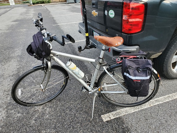
Bike loaded up and ready to roll
I rode about three miles to Towpath park, a ride I’ve done many times in recent years. The ride was uneventful, and I was soon setting up the GRA-7350TC on my new antenna mount. I used two 17-foot radials laid out on the ground and 25 feet of RG-316 coax. It was easy to get a 1.3:1 SWR on 20M.
Set up and on the air in the park
To see how it works, I set up my Penntek TR-35 on a nearby park bench. Tuning around I found some POTA activators to call. I ended up working three of them. It was fitting that one of my contacts was with Jim N4JAW. Jim is a bicycle/ham radio enthusiast I wrote about in a recent post. (Jim told me later that he was also bike-portable. You can read about his POTA activation operation and our QSO on his Ham on a Bike blog.)
My Penntek TR-35 set up on a park bench
Before tearing down, I checked the other bands with an antenna analyzer. I was able to get good matches on 30M through 12M. The 10M band was a little finicky. I didn’t use my longer radials, so I knew 40M would be tough.
Happy with the results, I loaded up the bike for the ride back to my truck.
Wrapping Up
I have a few takeaways from today’s ride:
The antenna mount worked great. However, using a PL-259 to BNC-F adapter on the antenna mount caused some clearance issues. It was a little tricky connecting the coax. I need to try using a right angle adapter next time.
The new panniers were easy to put on and take off the bike. Having a little extra room is a plus.
My short ride today was no Tour de France, but it reminded me how much I enjoy riding my bike. Yep. I definitely need to do more bike-portable outings this year.
My (far) better half and I spent the weekend in Central Pennsylvania watching the grandkids, while our second harmonic and her husband were off celebrating their anniversary. Of course, I took some radio gear along to do some QRP-portable operating while I was out there.
I had a brief window of opportunity on Saturday morning, so I drove to the Falmouth Access boat launch along the Susquehanna River to activate the Captain John Smith National Historic Trail (US-4567). Since we used the (far) better half’s car this weekend, I used this opportunity to try out my Gabil GRA-7350TC vertical and magnetic mount on her car for the first time. I also brought along my trusty Penntek TR-35 (5 watts, CW).
The Gabil GRA-7350TC & mag mount on my (far) better half’s car, while activating the Captain John Smith National Historic Trail (US-4567)
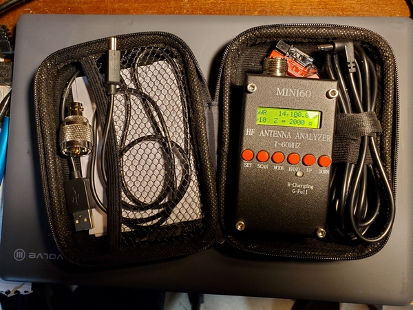
To facilitate tuning the vertical, I used a recently acquired Mini60 analyzer I bought off AliExpress. It’s cheap and a little quirky, but it’s small and its simple SWR readings got the job done. I started on 40M and got the SWR down to 1.3:1 without adding radials. That’s better than I had ever gotten on my pickup truck. I guess the roof on my XYL’s little SUV provides a better ground plane than my truck.
The Mini60 Antenna Analyzer. I found a case on Temu just the right size to hold the Mini60 and some accessories.
Band conditions were generally lousy, and there was some horrendous local noise in 40M and 20M. I didn’t experience any noise issues the last time I activated from here. Despite all that, I managed to scrape together 17 contacts in about 35 minutes, including one with F4ILH on 17M. Also, thanks to W5KEB for working me on two bands. (My apologies to a couple of hunters I couldn’t pull out of the crazy noise in 40M and 20M.)
Even though the bands weren’t too hot, I was pleased with the performance of the Gabil antenna. It’s another good antenna option when I’m using my (far) better half’s car (or any car, for that matter).
Back in 2017 I built my 19-foot wire vertical, which was my go-to portable antenna for about 4 or 5 years. The concept was simple: It functions as a base-loaded resonant vertical on 40M & 30M and as a random wire on 20M and up. The matching unit contains a tapped toroid for 40M & 30M and is fed through a built-in 1:1 choke. It occurred to me I could do something similar with the 12-foot telescopic whip and homebrew loading coil I’ve been using on my truck of late.
My 12-foot whip setup is resonant on 40M through 17M. You’re probably thinking: “Why not just bypass the loading coil and adjust the length of the whip for 15M through 10M?” Well, being as lazy as I am, that would make band changes a little more involved than I want to deal with. I like having some “frequency agility,” and I’m not above using an ATU to achieve that.
To emulate the scheme I used for the 19-foot vertical, I just needed a choke at the input to my homebrew loading coil. (I could probably go without the choke, but I wanted to keep the coax from becoming part of the antenna.) So, I use the 12-foot whip as a base-loaded resonant vertical on 40M through 17M. For 15M through 10M, I would bypass the coil and use an ATU.
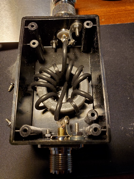
To test this out, I threw together a choke using parts I had on hand. I wound 10 turns of RG-174 on an FT-140-43 toroid. A Radio Shack project box I had in my stash of parts was the perfect size to house the toroid. (I bought it a decade or two ago, and it was still unopened in the original Radio Shack packaging.) Since I installed SO-239 connectors on each end, I had to use an adapter to connect the choke to the SO-239 on the antenna. To hold the coil in place, I wedged a piece of foam packing material between the lid and the core. The completed choke is functional, albeit a little cheesy-looking.
The choke is 10 turns of RG-174 coax on an FT140-43 toroid.
My first test using the 12-ft whip on the higher bands was a success. While activating Ridley Creek State Park (US-1414, KFF-1414), I used my KX3 (5 watts, CW) and installed the choke at the antenna feedpoint. On 40M through 17M, the loading coil functioned as it normally does. On 15M, 12M, and 10M, I bypassed the coil entirely and relied on the KX3’s internal ATU to load up the whip.
The choke installed at the antenna’s feedpoint
The KX3 easily found matches on all three bands, and my results on the air were encouraging. On 15M, I worked stations in Poland, Belgium, France, Ukraine, Germany (3), and the Slovak Republic. I made two stateside contacts on 12M. Up on 10M, I worked some more DX: Germany (2), Italy, and Czech Republic. One of the German contacts was park-to-park.
I’ve used this arrangement on a few more activations since then, including Winter Field Day. My results have been consistently good.
I haven’t done any modeling, but the 12-foot whip seems to be a pretty good length for operating like this. It’s just a little longer than a ¼-wave on 15M and a little shy of ⅜-wave on 10M. On 12M, it’s somewhere between ¼ and ½-wave; so it isn’t resonant on any of the bands of interest.
Although I was pleased with these initial results, I might do a little more tinkering with this setup. I’m toying with repackaging the choke to make it a little more weather resistant. I encountered some rain during the first activation using it. There was no damage to the choke at all, but I always have a tendency to over-engineer things—it keeps me occupied and out of trouble, I suppose.
No scientific breakthrough here. Just a lazy guy “force feeding” a fixed length whip to squeeze a few more bands out of it.
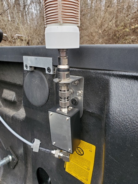
During a recent activation, my beloved MFJ 12-foot telescopic whip came apart. I’ve had it for a long time, so I was really disappointed when it broke. I specifically designed my homebrew loading coil to pair with a 12-foot whip. With this setup, I can work 40M through 17M by changing the tap on the coil. I don’t need to adjust the whip. These bands match the bands covered by my Penntek TR-35.
When the old whip broke, I salvaged the parts and tried to put it back together when I got home. No joy was to be had. However, all was not lost.
Although 12-foot telescopic whips aren’t aren’t as widely available as the ubiquitous 17-foot whip, I found one in stock at Ham Radio Outlet. After placing my order, I had the antenna on my porch 24 hours later on Christmas Eve. (I have no financial interest in HRO. I’m just a very satisfied customer.)
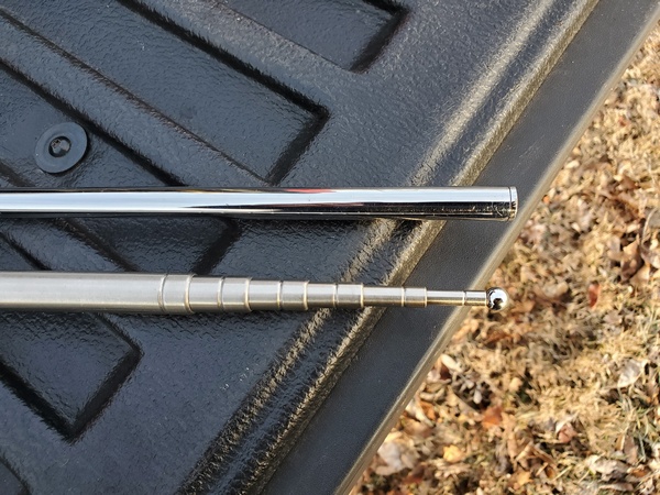
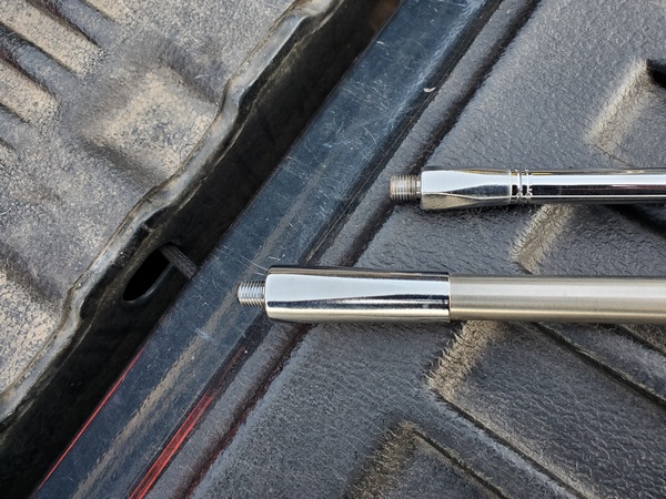
This new whip is an MFJ-1977, and it’s distinctly different from my old MFJ-1956 whip. The new whip’s construction is the first obvious difference. Additionally, the stainless steel has a less polished finish. The MFJ-1977 is also a little heavier, and its collapsed length is an inch or two longer than the older whip. In the pictures below, the older MFJ-1956 is on the top and the new MFJ-1977 is on the bottom:
The new MFJ-1977 had its maiden deployment at Norristown Farm Park (US-4363, KFF-4363). I used the antenna with my Penntek TR-35 (5 Watts) on 40M, 20M and 17M. As expected, the new antenna seemed to perform as well as its predecessor. After an hour and 10 minutes, I had 42 in the log with three DX contacts: two from France and one from Germany.
My old 12-foot whip saw heavy use, and it served me well. In the future, however, I plan to rotate whips occasionally. I extended my MFJ-1979 17-foot whip to 12 feet and marked it with a permanent marker. I did the same with my cheap 5.6M whip from AliExpress. Hopefully, having two other whips available will let me avoid beating up my 12-foot whip and extend its life.