In a previous post, I mentioned an antenna of mine that went missing. The antenna in question was a variation of my old Dollar Store Special. After I built a replacement, I found the original in my truck. No problem; as the name suggests, it wasn’t a huge monetary investment. This antenna is just another example of what can happen with some extra speaker and too much time on my hands.
The original Dollar Store Special (circa 2005) was the first of several projects to see if I could build a usable antenna from a 50-foot length of inexpensive speaker wire. The resulting antenna was a 50-foot radiator and some counterpoise wires configurable for 40M, 30M, and 20M. I used one of these for years as a backup antenna. As with all random wire antennas, it requires a tuner and, of course, some way to get one end up in the air.
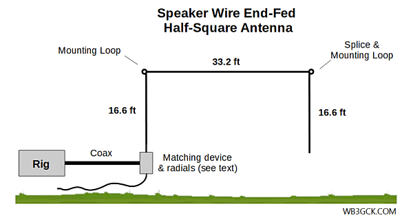
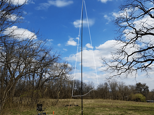
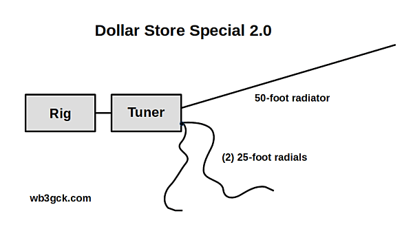
For this version, I went with a 50-foot radiator and two 25-foot radials. Besides being more simple to construct, it adds a little more flexibility. Space permitting, I can use the 50-foot wire in an inverted L, inverted V, or sloper configuration. When I need a quick way to get on the air, I can use a 25-foot radiator with a 25-foot counterpoise. (Elecraft documentation often recommends the 25-foot wires as a simple field antenna. [1][2])
I refer to this antenna—with tongue firmly planted in cheek—as the Dollar Store Special 2.0. That makes it sound like a bigger deal than it actually is. I should also note that I can no longer get speaker wire at my local dollar store. I have to spend a few dollars more now, but I kept the name anyway.
Construction is as easy as it gets:
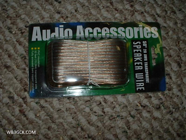
- Get a 50-foot length of two-conductor speaker wire. I use some inexpensive 24 gauge wire.
- Separate the two conductors.
- Cut one of the 50-foot wires in half.
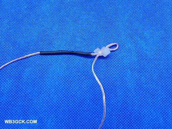
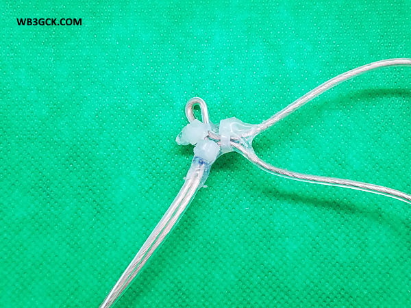
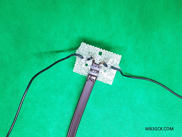
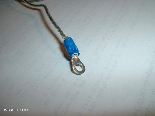
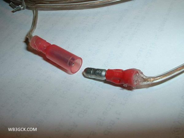
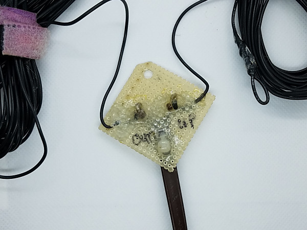
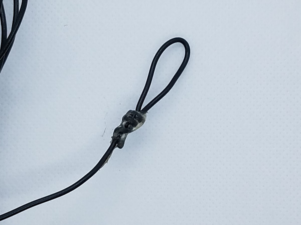
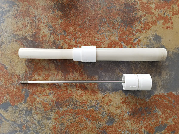
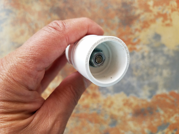
- I added a spade lug on one end of each wire and made a small loop in the other end.
- I also added some Goop® sealant/adhesive to hold the end loops together and provide some strain relief to the spade lugs.
The 50-foot radiator and two 25-foot radials cover 60M through 10M using my KX3’s internal tuner. Feeding it through a 4:1 unun, I can cover 80M through 10M. A 9:1 unun works well with this length also.
With a 25-foot radiator and a single 25-foot radial, my KX3 covers 40M through 10M with no problems. Adding in a 4:1 unun makes this a Rybakov 806 antenna that covers 60M through 10M. If you’re so inclined, you could partially unroll the 50-foot wire and use it as a second radial.
These results, of course, are highly dependent on the tuner you’re using. There’s nothing special about the 50-ft length. You can trim the radiator back to a length that provides an easier match. I stayed with the 50-foot length since I wanted to make use of the entire pool of speaker wire for these projects. Go with whatever works for you.
I’ve had good results with both configurations, and I have been impressed with the 25-foot radiator and 25-foot radial configuration. Although it’s slightly compromised on 40M, it seems to get out pretty well.
There’s nothing at all magical about this antenna; after all, it’s just three pieces of cheap wire. However, it makes a decent backup—or even a primary—antenna kit for portable use.
As I was writing this, I jotted down two more ideas for speaker wire antennas. Somebody stop me!
73, Craig WB3GCK
References:
[1] Elecraft KX3 manual, “Antennas,” p. 6
[2] Elecraft AX-Line Owner’s Manual, “Operating Tips,” p. 4