This week, my ham radio activity was focused on an emergency communications exercise with my local ARES-RACES group. I thought I’d do a post about the simple whip antenna I used with a dual-band radio. I cobbled this set up together a few years back and it has come in handy on several occasions.
During the exercise, I was operating indoors with easy access to our local repeaters. I was copying digital traffic using the Narrowband Emergency Messaging System (NBEMS), so a handheld radio wasn’t a good option. In this situation, a dual-band mobile radio and this little whip antenna hack were able to get the job done.
The Quickie Whip attached to my old Icom 207-H dual band radio
For the whip, I use commercially available, collapsible BNC whip antennas for the 2 meter and 440 bands. To connect the whip to the radio, I use a UHF-Male to BNC-Female right angle adapter I picked up on eBay. To help improve the efficiency, I attach two 1/4-wave counterpoise wires, one for 2 meters (about 19 inches) and one for 440 (about 6.3 inches).
Quickie Whip Antenna components: telescopic whip antenna, PL-259 to BNC-F right-angle adapter, and the modified 9V battery clip for the counterpoise wires.
To attach the counterpoise wires, I re-purposed a 9-volt battery holder. I just drilled out one of the mounting holes and used a small bolt and nut to attach the wires. The clip is just about the perfect size to snap onto the right angle adapter.
The antennas I use came from Smiley Antenna. I have 5/8-wave whips for 2 meters and 440, along with a halfwave whip for 2 meters. Although some of the antennas are specified to handle 50 watts, I generally use them only for 10 watts or less (in the interest of RF safety). If I need to run more power, I’ll go with an antenna placed a safe distance away.
I’ve used this simple antenna arrangement in several situations in recent years. It’s become a permanent part of my emergency communications go-kit.
I bought a lightweight telescoping pole on eBay a while back. It collapses down to 26 inches and weighs less than 12 ounces. Best of all, I only paid around $10 for it. While it was advertised as a 7.2-meter pole (approximately 23.6-feet), it actually measures about 19.5-feet when extended. This pole was just begging for some sort of antenna to support.
After trying different types of non-resonant wires with it, I decided to build some sort of resonant antenna. For quick excursions to the field, I often take the AlexLoop. However, sometimes it’s nice to have something a bit more frequency-agile. I wanted something that is easy to deploy and could cover the 40, 30, and 20-meter bands.
I started off planning to build a vertical with a 16.5-ft radiator to make it resonant on 20 meters. I could then build some loading coils to make it resonant on 40 and 30 meters. In the end, I went a slightly different way with this antenna.
With the lousy band conditions lately, I spend most of my time on 40 meters. I decided to take advantage of the full length of the pole. So, my concept was to use a 19-foot radiator with loading coils for 40 and 30. On 20M and higher, I would use the radiator as a random wire and use a tuner.
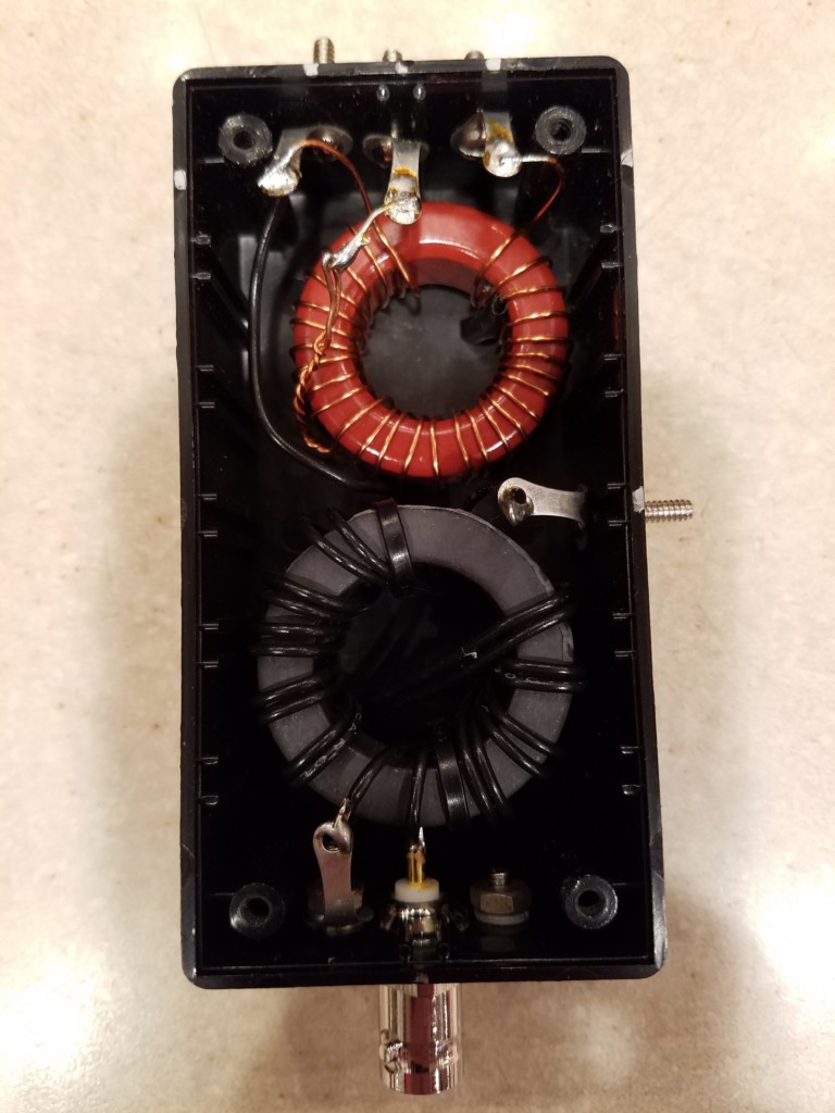
Schematic diagram of the matching network for the 19-ft vertical
As you can see in the schematic, I feed the antenna through a 1:1 choke, consisting of 10 bifilar turns of #22 hookup wire on an FT140-61 toroid. I calculated the values for the loading coil using some online calculators (see notes below). From there, I went through several iterations of testing and adjusting to arrive at the final values. For the 40M loading coil, I ended up with 29 turns of #22 enameled wire on a T130-2 toroid. I made a tap at 11 turns for the 30M band.
Interior of the matching unit
I mounted both coils in a small box and used some small bolts to make the tap points accessible for band changing. I also made a little jumper with alligator clips to short out various portions of the loading coil for the different bands.
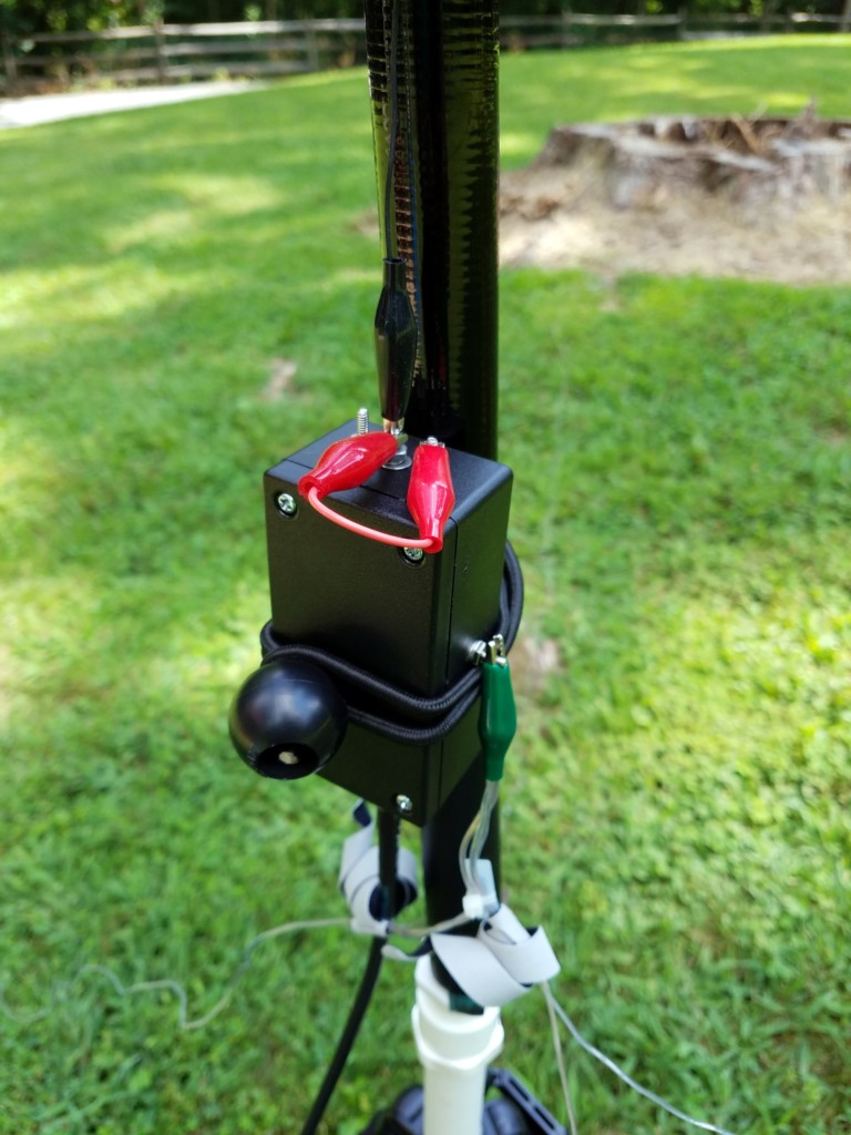
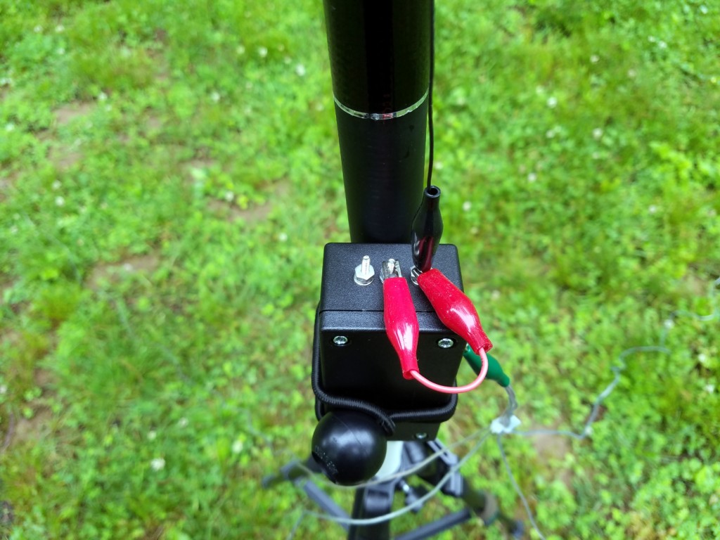
The matching network is attached to the pole with a small bungee cord. In this picture, the red jumpers are configured for the 30M band.
The pole won’t support much weight, so I built the 19-foot radiator from #26 Stealth wire (Part #534) from the Wireman. Because the pole is made from carbon fiber, I try to let the top of the pole bend over slightly, to keep the wire away from the pole. I don’t know how much influence the carbon fiber pole would have on tuning but I figure I’d avoid introducing another variable.
For radials, I used a 25-foot roll of cheap speaker wire and used it to throw together four 12.5-foot radials. Again, I grabbed what I had on hand and went with it. While the four radials seem to be working out OK, I plan to add a couple more for good measure.
I should note that all the materials here were selected based on availability in my junk box. So, there’s certainly plenty of wiggle room here for experimenting.
I made up a little tripod adapter out of some PVC pipe. One end slides over the post on my tripod, while the other end slides up inside the bottom of the collapsible pole. I also found a screw driver with a handle that fits nicely inside the bottom of the pole. So, for ground-mounting, I can just shove the screwdriver in the ground and place the pole on top of it. This works surprisingly well and allows me to leave the tripod at home.
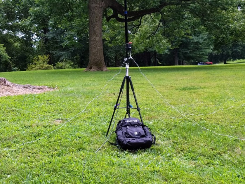
Vertical mounted on a tripod. My backpack is attached to the bottom of the tripod to help stabilize it in the wind.
After considerable tweaking I ended up with SWRs of less than 2:1 across the entire 40M band and less than 1.5:1 across the 30M band. On 20M and higher, the tuner in my KX3 loads it up with no problems.
The vertical ground-mounted. The pole is light enough to be supported by a screwdriver shoved into the ground.
I’ve been very pleased with the results on 40M so far. It seems to radiate pretty well. I’ve also made contacts on 30M and 20M but, honestly, I need to use it more on those bands to get a better feel for the performance. It’s hard to evaluate antennas when the band conditions are as poor as they have been lately.
Although the antenna works, there are a few things I would do differently, if I were to build another one:
My physical packaging could be better. While the enclosure I used is nice and compact, it’s a little cramped for experimentation. During development, coil adjustments were tough.
Separate coils for 40M and 30M would make the tuning much easier. The tapped coil was a challenge to adjust.
I like the form factor and easy setup of this antenna. I can set it up in a few minutes and it is very easy to transport by backpack or bike. Now to give it some more air time in the field.
Time will tell if it’s a keeper.
72, Craig WB3GCK
Notes:
Loading coil calculator: http://www.k7mem.com/Ant_Short_Dipole.html (Note: The calculator I originally used for this project is no longer online. This calculator should work. Just use one leg of the dipole.)
[This is an updated version of a post that appears on my old website. – WB3GCK]
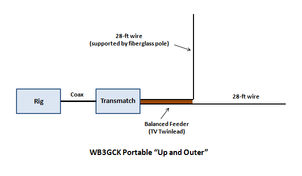
Something about the “Up and Outer” antenna has fascinated me since I first came across it in the 1974 edition of the ARRL Antenna Book. This antenna, which was once popular many years ago, is about as simple as it gets. Simply put, the Up and Outer is a dipole or doublet where one leg is vertical while the other leg is horizontal. Although it seems to be overlooked by Amateurs these days, this antenna offers some significant benefits:
It’s a good limited space antenna since one leg of the doublet is vertical. It only requires half of the space that a horizontal doublet would take up.
When fed with balanced line and used with a suitable transmatch, it’s a good multi-band antenna.
It combines characteristics of both verticals and horizontal wire antennas. That is, it is good for both local and DX work.
It’s very easy to build and erect.
The “Up & Outer” is essentially a doublet with one vertical leg and one horizontal leg.
First, a little background on this antenna. According to some handwritten notes from QRP Hall of Famer, C. F. Rockey W9SCH (SK), this antenna goes back to the 20s and 30s. Lew McCoy W1ICP (SK) wrote about it in the October 1960 edition of QST [1]. He didn’t use the name, “Up and Outer;” he merely referred to it as a “limited space antenna.” McCoy recommended horizontal and vertical elements of 30-feet each for operation on 80-10 meters. He also recommended using an open-wire feedline to minimize losses. Information from McCoy’s article has appeared for years in the ARRL Antenna Book. (I first saw it in my 1974 edition [2] and it was still shown in the 1997 edition [3].)
W9SCH wrote a couple of articles about this antenna for SPRAT and appears to have coined the term, “Up and Outer.” In the first SPRAT article [4], Rock suggested using 1/4 wave elements for the lowest band and feeding it with either coax (for single band operation) or balanced line (for multi-band operation). In a follow-up article [5], Rock suggests pruning the horizontal element to equalize the current in the balanced feeder. He noted the imbalance when operating with the horizontal element close to ground. He started with 16-foot elements to cover 30-10 meters.
Another Hall of Famer, L. B. Cebik W4RNL (SK), wrote about a coax-fed version of this antenna for 10 meters [6]. Cebik built his antenna using aluminum tubing and referred to it as the “L Antenna.”
I also exchanged some correspondence years ago with Fred Bonavita K5QLF (SK), another QRP Hall of Famer and fan of the Up and Outer. He told me that W9SCH once mentioned using the copper ball from an old toilet float to top-load the vertical element of the antenna. I later came across a brief write-up by W9SCH on his Copper-Top antenna in the October 1995 edition of QRP Quarterly [7]. Using the toilet ball for top loading, Rock was able to reduce the height of his vertical element by 2-1/2 feet.
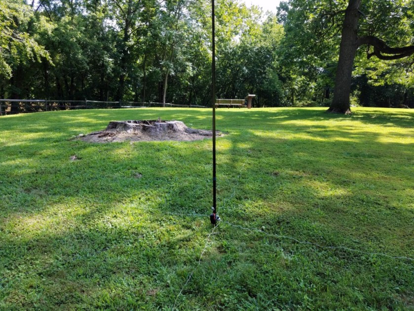
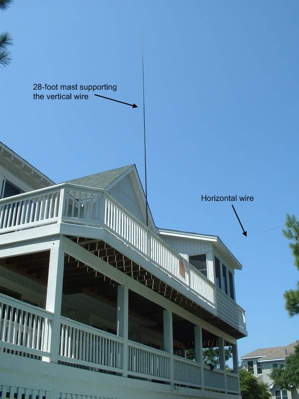
The “Up and Outer” antenna mounted on a 3rd-story deck in Corolla, North Carolina.
For me, the Up and Outer has turned out to be an ideal portable antenna to use while on vacation in a rented house on the Outer Banks of North Carolina. For several years I’ve used a 56-foot doublet with one wire supported by a 28-foot fiberglass telescopic mast and one 28-foot leg run horizontally. The vertical radiator is typically situated on a 3rd or 4th story wooden deck with the horizontal wire secured to a nearby tree or other support. For feedline, I use 25-feet of TV twinlead (the cheap brown stuff). Using either a homebrew Z-match tuner or an autotuner with a short run of coax to an external 4:1 balun, I’ve been able to use this antenna on 40-10 meters. Your mileage may vary. Depending on the transmatch you use, you might need to adjust the length of the feedline to get a good match on 40 meters.
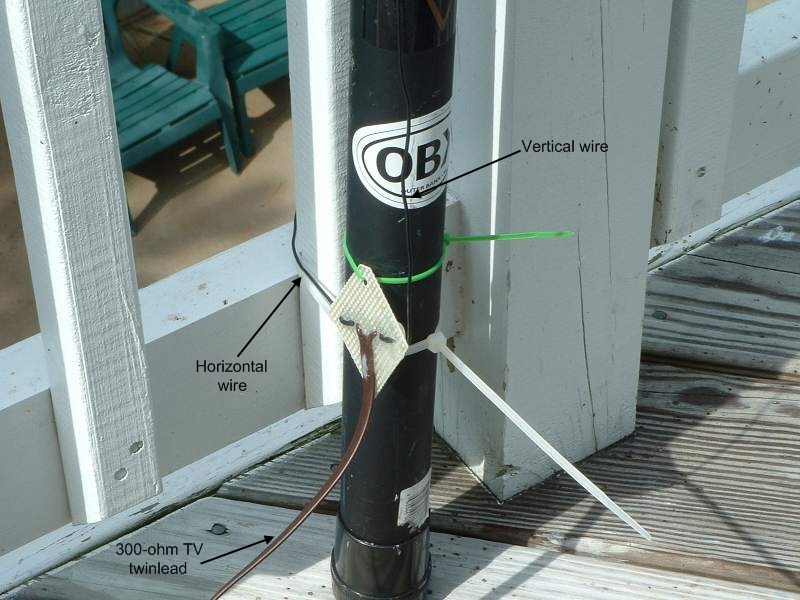
“Up and Outer” feedpoint
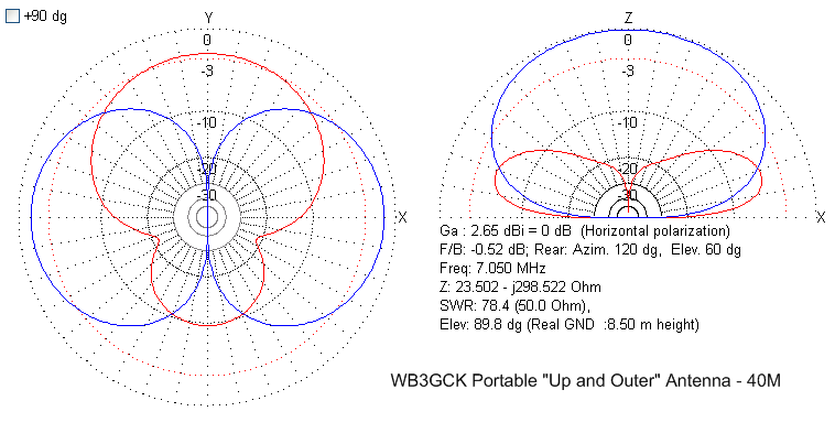
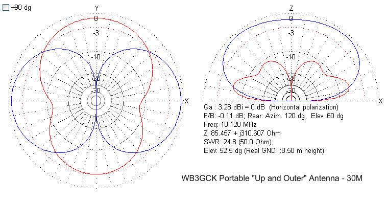
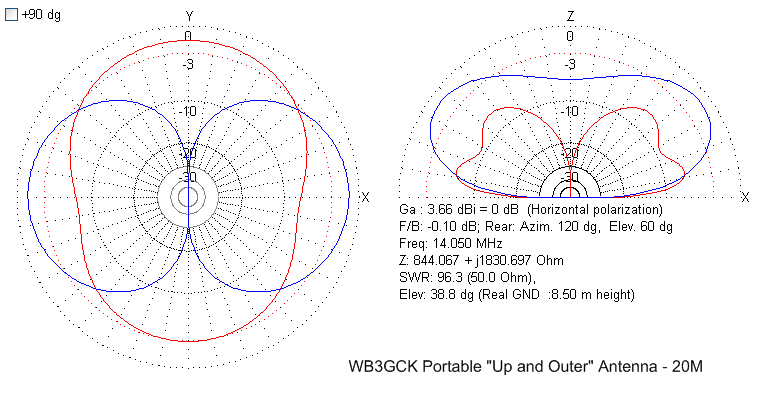
I did some quick modeling of a typical Outer Banks installation using MMANA-GL and you can clearly see the results of the combined horizontal and vertical elements. The horizontal polarity (shown in blue) shows lobes perpendicular to the axis of the horizontal wire, similar to a dipole. The vertical polarity (shown in red) shows a fairly low take-off angle and exhibits some slight directivity on 40 meters in the direction of the horizontal wire. This effect is due to the proximity to ground of the horizontal element and diminishes as you go higher in frequency. So, try to mount the Up and Outer as high above ground as you can.
“Up and Outer” 40M pattern“Up and Outer” 30M pattern“Up and Outer” 20M pattern
The modeling bears out my empirical results with the antenna. My version of the Up and Outer has worked very well for both stateside contacts and DX. In particular, it has been very effective for DX contacts on 30 meters. As an added bonus, the 56-foot doublet can also be pressed into service as a normal horizontal antenna in locations where the Up and Outer configuration isn’t possible. So, it’s like getting two antennas in one. Can’t beat that.
If you are looking for a limited-space antenna, give this obscure classic a try!
73, Craig WB3GCK
References: 1. McCoy, Lewis G. “A Limited-Space Antenna.” QST October 1960: pp 23-25. (Available in the ARRL online archives) 2. “The ARRL Antenna Book.” 13th Edition, 1974. Newington, CT. pp 187-188. 3. “The ARRL Antenna Book.” 18th Edition, 1997. Newington, CT. pp 7-15, 7-16. 4. Rockey, C. F. “Up and Outer.” SPRAT Issue #67 (Summer 1991): p 18. 5. Rockey, C. F. “A Four Band Up and Outer Antenna.” SPRAT Issue #69 (Winter 1991/1992): p 16. 6. Cebik, L. B. “Whips, Tubes and Wires: Building a 10-Meter L Antenna.” QST December 1999: pp 52-54. (Available in the ARRL online archives) 7. Rockey, C.F. “The Copper-Top Antenna.” QRP Quarterly, October 1995: pp. 40-41.
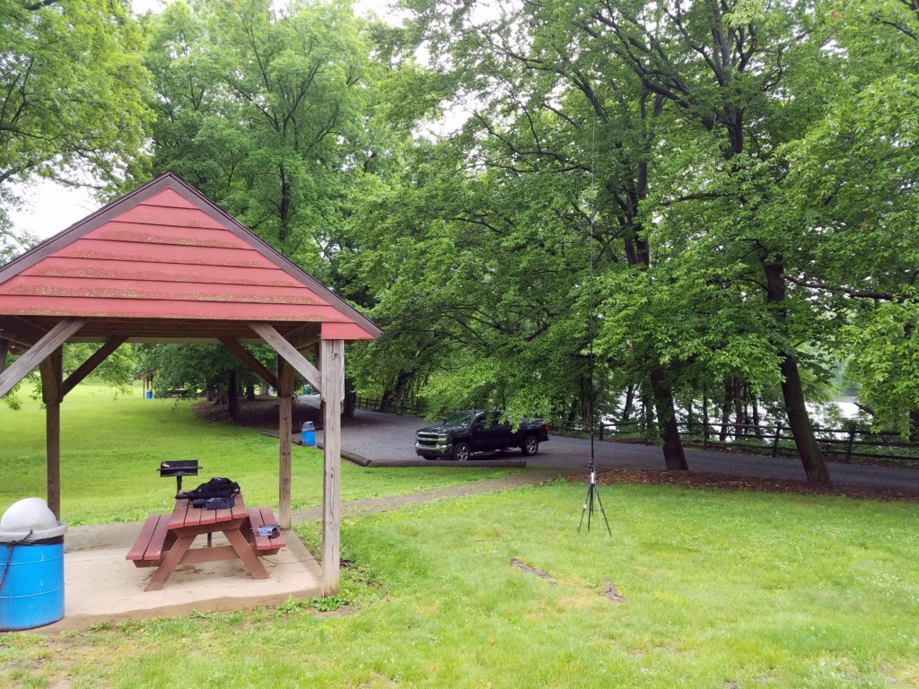
Carrying on from the initial testing I did last week, I went out for a bike ride yesterday and took my experimental vertical along. (I gave a general description of this antenna project in my previous post.) I rode a few miles up the Schuylkill River Trail and on to a park along the Perkiomen Trail.
I set up in a remote section of the picnic area and quickly took some readings on 40 and 30 meters with my antenna analyzer. I had done some tweaking to the loading coil but, unfortunately, both bands were still resonating too low.
My set up at Lower Perkiomen Valley Park. If you look closely at the S-meter in the upper right of the display, you can see the horrendous noise level on 40 meters.
I set up my KX3, intending to make some contacts. This, however, was not to be. There was a background noise level that was higher than I had encountered on a previous visit to this park. As I was tuning around, I looked over and saw that the wind had blown my antenna over. I neglected to bring anything along that I could use to stabilize the antenna and tripod. I set it back up but it wasn’t long before the antenna was on the ground again. After it blew over a 3rd time, I gave up. I packed up the bike and rode back down the trail to my truck.
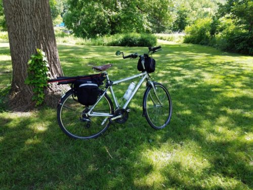
My bike loaded up for the trip home. No contacts today but at least I had a nice bike ride!
This morning I made another adjustment to the antenna’s loading coil and headed over to Valley Forge Park to test it. Like yesterday, it was somewhat breezy. This time, I hung my backpack from a hook on the bottom of the tripod to make sure the antenna stayed upright.
My set up at Valley Forge National Historical Park. I hooked my backpack to the bottom of the tripod to help stabilize it in the wind.
I took some antenna analyzer readings and found that the 40-meter band was now resonating right where I wanted it. I saw some improvement on 30 meters but it was still resonating below the band. Obviously, the tap for the 30-meter band is in the wrong place.
As I tuned around, it the bands seemed better this morning. I worked N5P in Texas on 20 meters. N5P was participating in the Museum Ships Weekend event from the National Museum of the Pacific War. I moved down to 30 meters and heard a couple of strong stations. I didn’t make any contacts there, though.
I called CQ on 40 meters and quickly got a call from N1PVP in Massachusetts. I remembered working Marino a couple of weeks ago. He always has a very strong signal into Pennsylvania. I wrapped up with a two-way QRP QSO with Alan AC8AP in Ohio.
Antenna-wise, I have to do some thinking about how to proceed with my experimental vertical. As I see it, I have a few options:
I could continue to tweak the existing coil. If I remove turns from the bottom of the coil while adding the same number of turns to the top of the coil, this would effectively move the tap point for the 30-meter band.
It might be easier to just re-wind the coil and add a few more tap points. I could do some testing to see which tap works the best.
I could always invoke the “do nothing” option. The SWR on 30 meters is only about 4.3:1, which is a trivial match for the KX3’s internal tuner.
In any event, the antenna is useful as it stands. I’ll take some time this week to consider my next move.
Some time ago, I bought a small, lightweight telescopic fishing pole from a Chinese vendor on eBay. It’s about 19.5 feet tall and collapses down to about 26 inches. It’s a great size for backpacking or transporting on my bike. It weighs practically nothing. In fact, it’s too light for supporting anything but a lightweight vertical wire. Although I have used it a few times to support various antenna configurations, I never really found one that was a “keeper.”
Since I had some time over the long holiday weekend, I scratched out a quick design for yet another vertical antenna and cobbled it together with parts I had on hand in my junk box. I designed it to operate as a base-loaded resonant vertical on both 40 and 30 meters. On 20 meters and higher, it operates as a non-resonant wire; thus, an antenna tuner is required on those bands. Along with the loading coil, the matching unit contains a 1:1 choke balun to isolate the feedline. Both the choke balun and tapped loading coil are wound on toroids and mounted in a small, plastic enclosure. The radiator is a 19-foot piece of #28 wire. I could have shortened the radiator to make it resonant on 20 meters also, however, I went with the longer radiator for better performance on 40 meters. I used four 12.5-foot radials that I made from a 25-foot roll of cheap speaker wire.
The antenna I was testing. The white piece between the telescopic pole and the tripod is an adapter I made from PVC pipe.
Normally, I like to use the “build a little, test a little” approach. Since I don’t have the luxury of space at home for antenna testing, I just took my chances and built the whole thing. I headed out to a local park yesterday to give it the “smoke test” and see how close I came with my loading coil design.
My operating location on a cloudy and rainy morning
It took less than 5 minutes to set it up. I used an antenna analyzer to take some initial measurements. On both 20 and 30 meters, the resonant frequencies were low and fell outside the band. I still have some work to do there. On 20 meters and up, the KX3’s tuner loaded it up easily.
The antenna matching unit. The red jumper is used to change bands.
Next, I wanted to put it on the air. I started on 40 meters and used the KX3’s tuner to tweak the SWR. I called CQ a few times and eventually got a call from K4ALE in Virginia. Bevin said I was 559 with QSB. Despite the poor band conditions, we had a nice chat.
After I signed with Bevin, I set the antenna for 30 meters and kicked in the KX3’s tuner. I called CQ and was quickly answered by NN4NC in North Carolina. Jim gave me a 569. At times, the band would fade to just about nothing. As I was chatting with Jim, some drizzle started blowing in under the pavilion where I was sitting. So I signed with Jim and quickly packed up.
I’ll be doing some adjustments to the antenna over the coming weeks. It looks, though, that this could be a useful portable antenna, once I get the loading coil straightened out.
Since this is a work in progress, I left out the details for now. After I get the antenna working as intended, I’ll provide a detailed description, schematic and parts list in a future post.
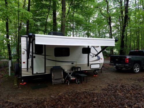
We recently retired our old pop-up tent trailer and acquired a small hard-sided travel trailer. The antenna I used with the pop-up camper evolved over 19 camping seasons to a pretty decent all-band antenna. It covered 80 through 6 meters (with a tuner) and required almost no space at all when deployed. I needed to come up with something similar for the new trailer.
My new travel trailer on its maiden voyage to Codorus State Park in south-central Pennsylvania.
For the first outing, I went with a modified version of the Pop-Up Vertical. In a nutshell, I used a 30-foot vertical wire, fed through a 4:1 unun. The ground side of the unun was attached to the frame of the trailer. My 31-foot Jackite pole supported the wire. I used my drive-on mast support to hold up the pole. Instead of parking one of the trailer’s tires on top of the drive-on mount, I put it under one of the trailer’s stabilizer jacks to hold it down.
This is the drive-on mount that supported the Jackite pole. The black box is the 4:1 unun. To the left of the unun, you can see the clamp for the ground connection to the trailer’s frame.
On our first camping trip with the new trailer, I was able to quickly set up the antenna. For the feedline, I used an 18-foot length of RG-8X coax, which I ran through a window to the dinette table inside the trailer.
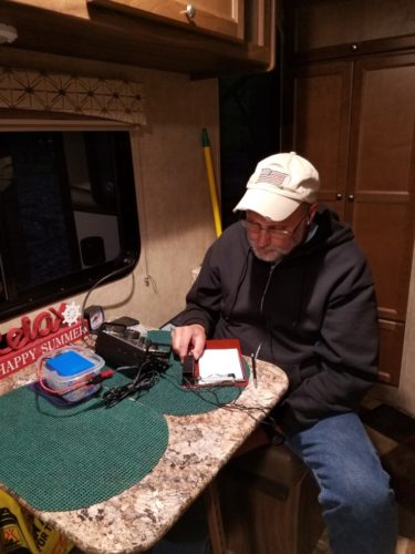
Using the tuner in my KX3, I was able to get the antenna to load up on 80 through 6 meters. The 80M band was a bit touchy but the KX3 was able to get to 1:1 SWR. I had a nice CW chat on 40M with N1ESZ up in Connecticut. Tony gave me a great signal report. This thing appeared to be radiating! I was a little concerned because part of the antenna was close to the metal wall of the trailer but my signals were going somewhere.
WB3GCK operating from the new trailer. My XYL took this picture while I was working N1ESZ on 40 meters.
I made another half-dozen QSOs on 80, 40 and 20 meters over the weekend. The antenna performed well during some lousy band conditions but I did encounter some issues.
There was some noise that appeared about every 25 or 30 KHz that moved around a bit. It was loudest on 40 meters. I suspect that the trailer’s converter, which converts 120 VAC to 12 volts DC, is the culprit. My antenna was pretty close to the trailer’s power cable that connects to “shore power.” I could have picked up the noise from there. Also, during a QSO with KK0I in Wisconsin on 40 meters, I noticed that a LED on the trailer’s control panel was flashing in unison with my CW. My 5-watt signal was finding its way into the trailer’s circuitry. The extra amenities and gadgets in the new trailer are convenient but not necessarily radio-friendly.
Not unlike the antenna on my old camper, this will be a work-in-progress. On our next trip, I’ll be relocating the antenna to a corner of the trailer that’s further away from the electrical stuff. I also have some tweaks to the antenna configuration that I want to try. If all else fails, I’ll just have to mount the antenna further away from the trailer.
[This is an updated description of the drive-on antenna support that I have been using for many years. This version originally appeared in the July 2016 edition of QRP Quarterly in the “Idea Exchange” column and most-recently in the October 2024 edition of Radio ZS, The Journal of the South African Radio League. You can still find the older article here. A revised, “step-by-step” version appeared in ARRL’s On the Air Magazine (May/June 2024 edition). ]
Here’s a simple, inexpensive drive-on mast support that I have been using for more than ten years now. It’s been particularly handy for quick trips to the field, such as National Parks on the Air (NPOTA) activations.
Over the years, telescopic fiberglass poles have become popular as portable supports for lightweight antennas. Two popular suppliers of these collapsible poles are Jackite (http://www.jackite.com/) and SOTABeams (http://www.sotabeams.co.uk/). I typically use my 31-foot Jackite pole to support a vertical wire along the outside of the pole. I have also used them to support lightweight dipoles and a variety of end-fed wire antennas.
One trip to your local hardware store will get you everything you need for this project. To support a 31-foot Jackite pole, here’s what you’ll want to buy:
1-1/4 inch floor flange
18-inch length of 1-1/4 inch threaded steel pipe
(4) 1/4-20 x 1-1/2-inch flathead bolts
(4) 1/4-20 nuts
(4) 1/4-inch flat washers
(4) 1/4-inch lock washers
18 to 24-inch length of 1×8 lumber (I used a piece of maple. A piece of 1×6 lumber would also work)
[NOTE: I’ve heard that the dimensions of newer Jackite poles may be different. Use the dimensions given here as a general guide, and be sure to double-check the dimensions of your particular pole before buying materials.]
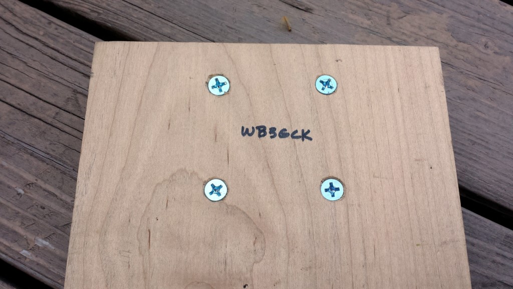
Figure 1. Drill 4 countersunk holes for the floor flange at the end of the board.
Assembly is pretty straightforward. Drill four holes to mount the flange to the board. The flathead bolts go in from the bottom. You need to countersink the bolts so they will flush with the bottom of the board. Attach the flange with the flat washers, lock washers and nuts. That’s about it.
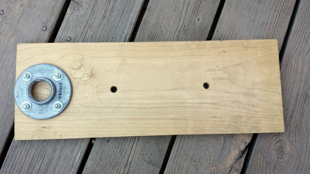
Figure 2. Here is the floor flange mounted on the board.
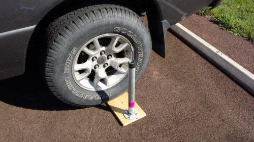
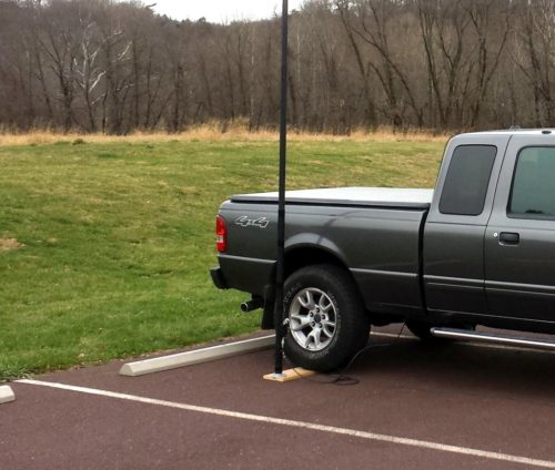
To use the mount, I just set it on the ground and run one of my vehicle’s tires up on it. Next, I screw the threaded pipe into the flange. Once the pole is fully extended and the bottom cap removed, I just slide the pole over the pipe. For my 31-foot Jackite pole, I use a little electrical tape on the pipe to give a snug fit.
Figure 3. Drive onto the mount and screw in the pipe.Figure 4. Drive-on mast in use supporting a vertical wire.
You can also adapt this for other size poles. For my 28-foot Jackite pole, for example, I use a 1-inch pipe. For my 20-foot Black Widow pole (https://www.bnmpoles.com/), I use a 3/4-inch pipe. You can buy reducers (adapters) in the plumbing department that will allow you to use the smaller diameter pipes with the 1-1/4 inch flange. If you only use one particular pole, you can always buy a smaller flange and build your mount with that.
This design is more than sufficient for a lightweight, telescopic fiberglass mast. If you need to support something heavier, like a steel mast, you’ll need a more robust support than this.
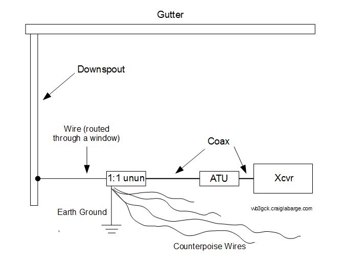
[A ham friend of mine recently asked me for the details of how I use my rain gutter and downspout as an antenna. I originally did a write-up on it in 1994. That article found its way into several ham radio publications and newsletters. Most of the original article is still relevant but I have made some changes in the way I feed the “antenna.” So, here’s an updated description of my Downspout Antenna. – WB3GCK]
After years of trying to come up with a good way to get on the HF bands from my little townhouse (without attracting a lot of attention from my neighbors), I started experimenting with using my aluminum rain gutter and downspout for an antenna. The results have been surprisingly good. In fact, it has turned out to be the ultimate low-profile antenna!
The downspout has a vertical run of about 16 feet, connecting the horizontal rain gutter which is about 16 feet long across the front of the house. Including the feed wire into the shack, the total length is in the neighborhood of 42 feet; over a quarter wavelength for 40 meters and almost a half-wave for 30 meters. The house is made of brick, so the entire system is isolated from ground.
WB3GCK Downspout Antenna
I use my downspout like a random wire antenna, using a commercial autotuner (or internal tuner, in the case of my KX3). I feed the antenna through a homebrew 1:1 unun. I use a short run of coax between the unun and the autotuner on my operating table. A length of #22 stranded hookup wire is used to connect the output of the unun to the downspout outside.
To connect the wire to the downspout, I first sanded the downspout and connected the wire using three sheet metal screws. I used multiple screws to help ensure a low resistance connection. After making the connections to the downspout, I sealed them up using an adhesive/sealant called Goop. Goop is available at most hardware stores.
With the downspout behaving essentially like an end-fed wire, it really helps to work this type of antenna against a good ground. Fortunately, my basement operating position is only a few feet away from where the water supply pipe enters the house. I used a piece of 1/2-inch copper pipe as a ground bus between my operating position and the incoming water pipe. A tinned copper braid strap and a couple of ordinary automotive hose clamps were used to connect the bus to the water pipe. A short braid strap connects the ground stud on the unun to the copper ground bus.
For good measure, I attached counterpoise wires to the ground stud of the unun; one each for 40, 30, 20, and 15 meters. The counterpoise wires are made from garden variety stranded hookup wire cut to a quarter-wavelength. I just run these wires around the shack, hiding them under the rug. Operation on the 80 meter band has been successful using just the ground bus.
How well does it work? During the first few months of operation, I worked 49 states; all with 5 watts or less. I’ve also worked a bunch of DX stations (though I’m more of a casual rag chewer than a DX-chaser). The length of the “antenna” is somewhat short for 80 meters, but performance on that band has been a big surprise. Signal reports on 30 and 40 meters, my primary bands, have been consistently good. In fact, the downspout has been my main antenna at home for more than 20 years.
While this arrangement has served me well, it is not without an issue or two. I find that it helps to clean up and re-do the connections at the downspout periodically. Typically, I do this maintenance every other year or so. Also, I have noticed that my local noise levels on 80 and 40 meters have steadily increased over the years. I attribute this to the proliferation of electronic gadgets both in my house as well as my neighbors’ houses. Those bands are still usable, though.
Some words of caution are in order, however, if you plan to use your rainspout as an antenna:
Make sure your gutter and downspout are isolated from ground.
Make sure there is solid electrical continuity between the various sections of your downspout and gutter. Mine are fastened with pop rivets (not the greatest for RF work, but they appear to be doing the job.)
Watch your power. I wouldn’t recommend running a kilowatt into your rainspout. Ham radio is fun, but not worth burning down your house.
Make sure people and pets won’t come in contact with the “antenna” while you’re transmitting. This isn’t too much of a problem at QRP power levels, but be careful.
So, if you find your HF antenna options are limited by either space or legal restrictions, take a look at the outside of your house. There just might be a free multi-band antenna hanging out there!
Here’s a little hack that serves no real purpose. I’ll tell you about it anyway.
I recently built the T-Tone Code Practice Oscillator (CPO) kit from Morse Express. It’s a handy little addition to the shack for adjusting straight keys or testing keyers. After building it, I just adjusted the audio frequency for a pleasing tone. Most people would have just left it alone at that point. I’m not most people.
I started to do some thinking, which is a dangerous practice that can sometimes lead to unexpected consequences. I wondered how the frequency of CPO compared to the sidetone of my FT-817. There was no particular point to this mental exercise other than idle curiosity.
Now, I certainly could have keyed both the CPO and the FT-817 and done a comparison by ear. I could have just adjusted the CPO by ear to match the FT-817. But what fun would that be? I was curious about the exact audio frequency of the FT-817’s sidetone, so I opted to do some experimenting.
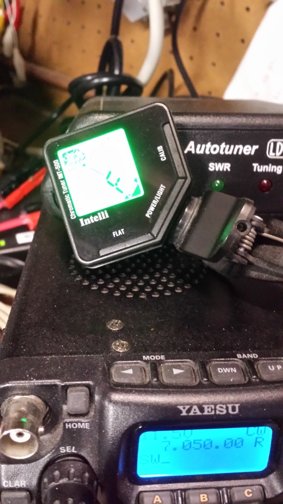
Having been playing guitar for more than 50 years, I have acquired a gadget or two over the years. One of those gadgets is a clip-on guitar tuner. I can clip this clever device on the headstock of my guitar and, by sensing vibrations, it will tell me what note I’m playing and whether the pitch is sharp or flat. I figured I could use this thing as an audio frequency meter of sorts.
First, I laid the guitar tuner on top of the FT-817’s speaker and keyed up. That indicated that the pitch of the sidetone was an F note. Consulting a conversion chart I found on the Internet, that equates to 699Hz. I seemed to recall that the FT-817’s sidetone was somewhere around 700Hz, so that seemed about right. I was sure I was in the right octave.
Guitar tuner on top of the FT-817
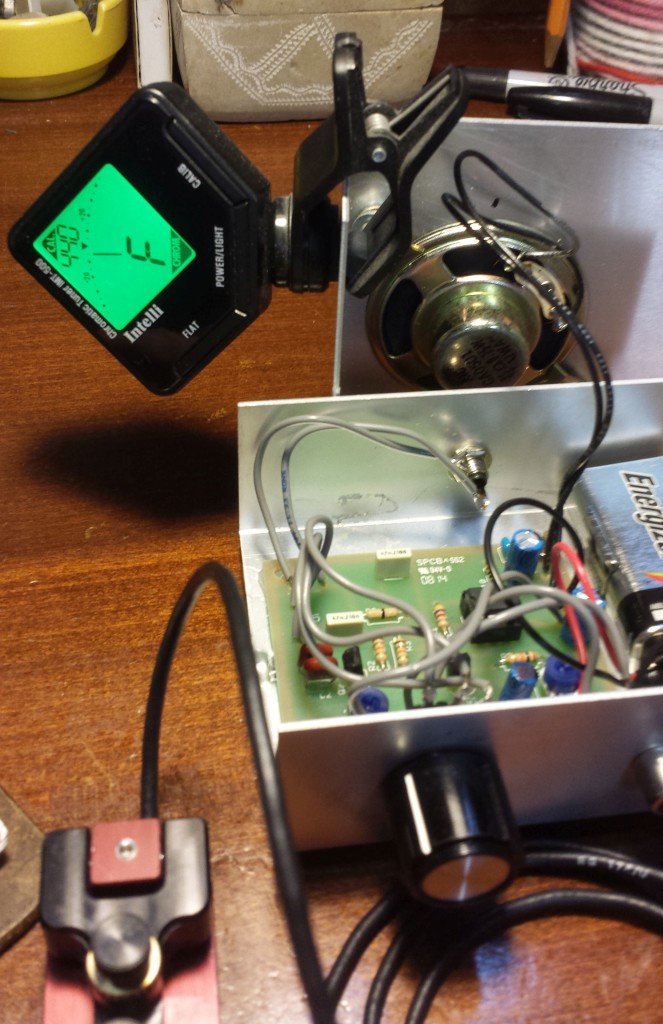
Next I took the lid off of the CPO and clipped the guitar tuner on it. It initially indicated that the CPO was tuned to F#. That equates to a frequency of 740Hz. I tweaked the CPO’s frequency adjustment pot to F, matching the FT-817. A side-by-side comparison of the CPO and the FT-817 showed that I was successful.
Guitar tuner clamped onto the lid of the code practice oscillator
So, what’s the point of all this? None really. Is there a practical use for this? Probably not. Does it really matter that my CPO matches the sidetone of my radio? Nope. I just had one of those “I wonder what would happen if…” moments. Now I know.
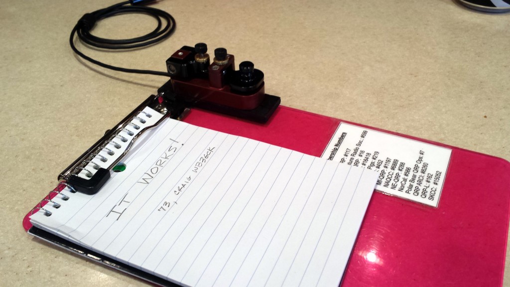
As I mentioned in an earlier post, I bought the little American Morse MS2 straight key intending to somehow magnetically attach it to the clipboard I use for portable operating. It took some thinking but I came up with a workable solution. I might come up with a better solution in the future but, for now, it should suffice.
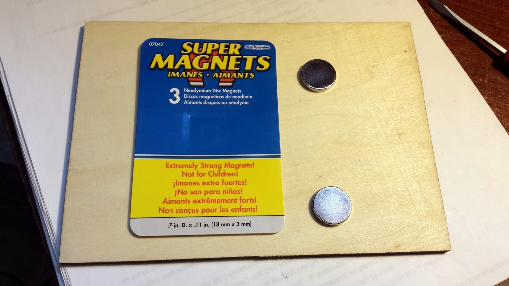
What I set out to do was build a wooden mount that could attach the MS2 that held two magnets that lined up with the steel washers on the clipboard. I had a couple of “super magnets” that I planned to use. The problem I ran into is that the magnets are almost too strong to attach directly to the washers. My solution was to enclose the magnets within the wood base.
Super magnets. Boy, these things are powerful!
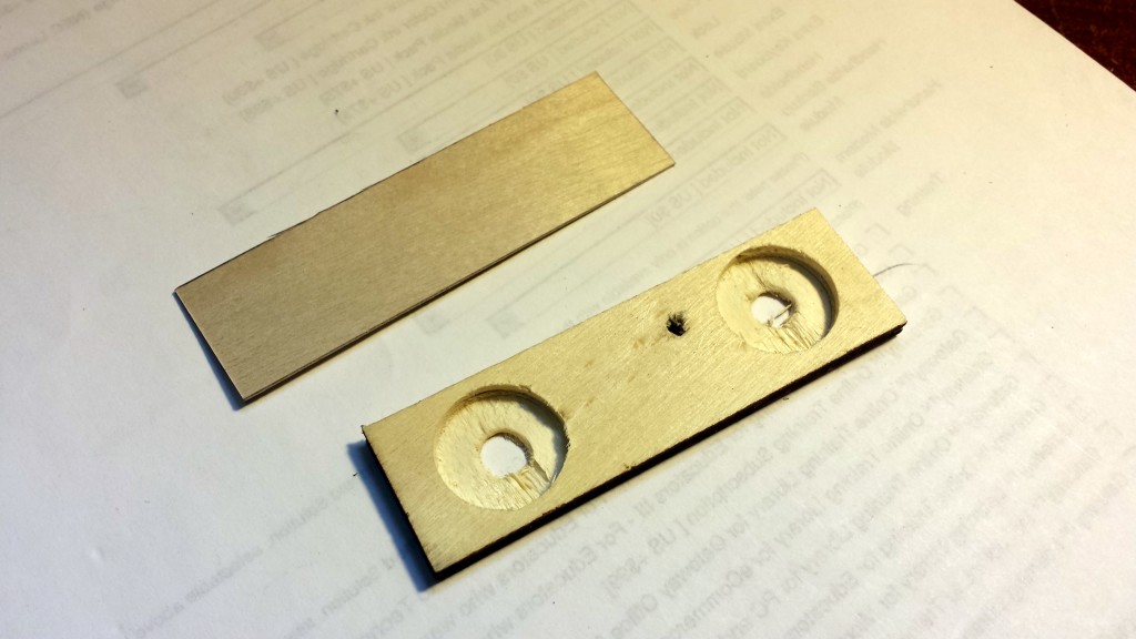
I cut a 1×3.25-inch piece of 1/8-inch plywood. Then I drilled two 3/4-inch holes just deep enough to fit the magnets. After placing the magnets in the holes, I glued on a thin wood veneer. This puts some extra spacing between the magnets and the washers on the clipboard. After drilling a mounting hole for the MS2, I sprayed on a couple of coats of paint.
Wood pieces prior to assembly
After letting the paint dry, I went to attach the key to the base. Oops! I drilled the mounting hole from the wrong side of the mount. My first inclination was to putty it in and repaint. However, I decided to leave it there as a constant reminder to always measure twice and drill once!
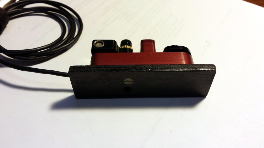
MS2 attached to the magnetic base. Don’t look too closely or you might see the drilling mistake I made.
The mount actually works well. The concealed super magnets hold the key firmly to the clipboard without the need for excessive force to remove it. Once I free up some time, I’ll give it a thorough test out in the field.