Round Two with the AD8HK EFRW

A while back I purchased one of AD8HK’s end-fed random wire (EFRW) antennas. I tried it for the first time during my ill-fated Flight of the Bumblebees (FOBB) outing. With everything that went wrong that day, the AD8HK antenna certainly deserved a better evaluation—at least one where I wasn’t in a panic over problems with my newly acquired Elecraft KH1.

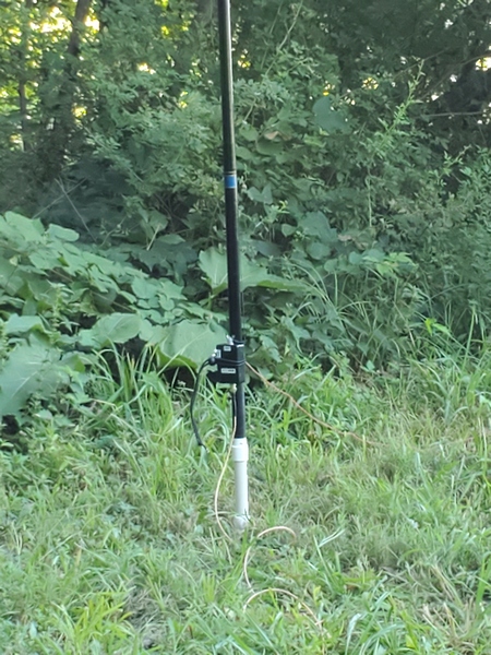
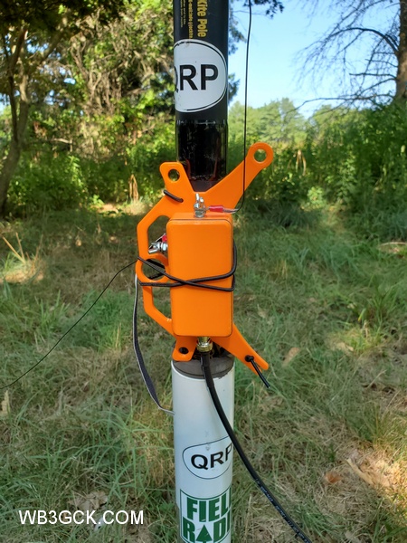
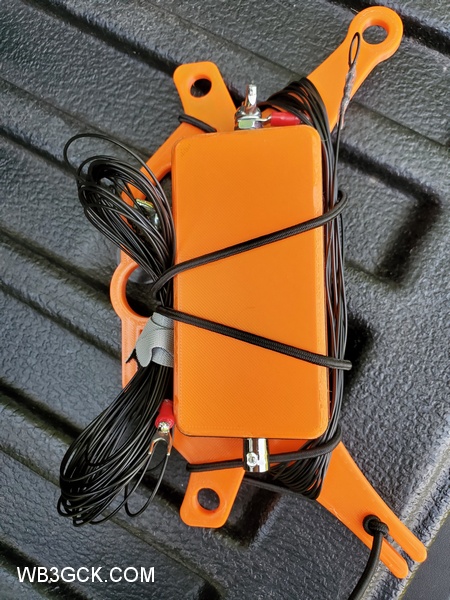
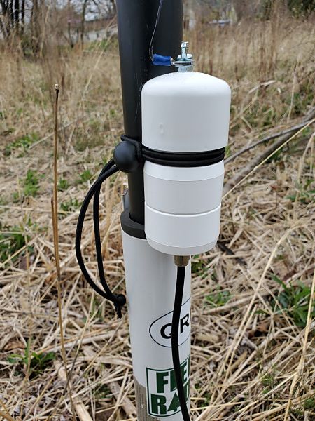
The AD8HK EFRW is a really slick little antenna. It consists of a 15-foot radiator and a 7.5-foot counterpoise wire. It has a neat 3-D printed winder for the wires that also incorporates a 4:1 unun and BNC connector. It’s compact and well-built. AD8HK Antenna Systems sells this antenna (and other offerings) through eBay.

During my infamous FOBB outing, I fed the antenna with 6 feet of RG-316 coax. It loaded up on 30M through 15M, but neither my KH1 nor my Elecraft T1 tuner could find a match on 40M. I’m not sure what the issue was, but I didn’t have much time to look into it.

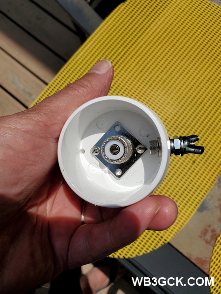
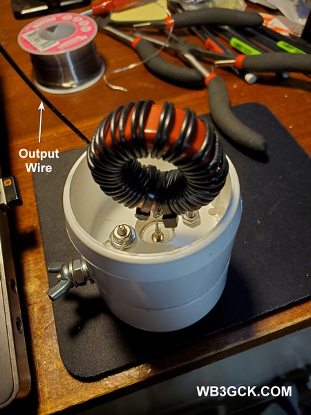
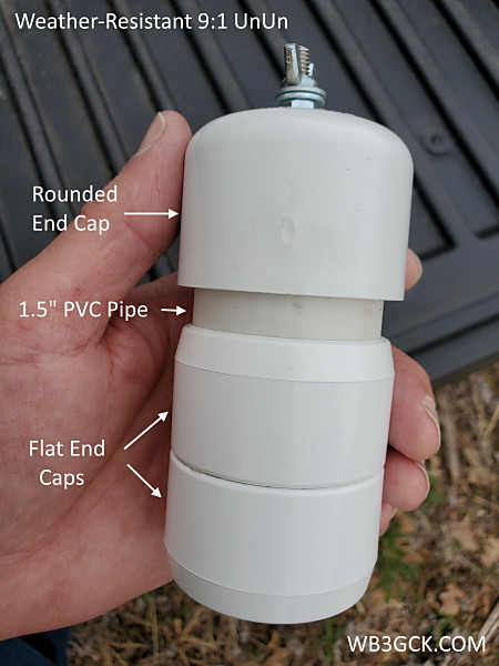
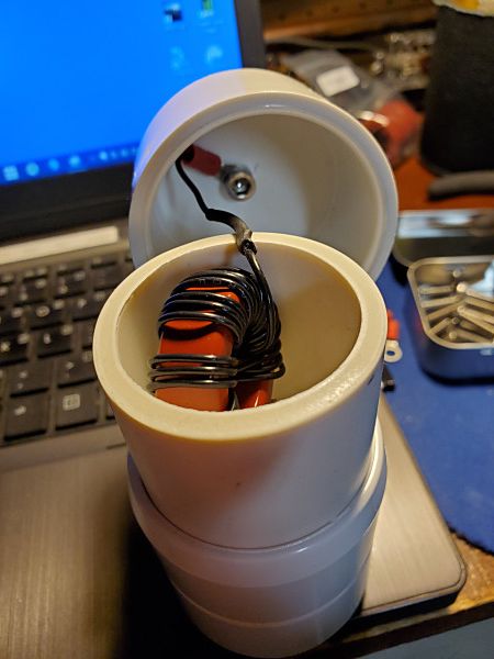
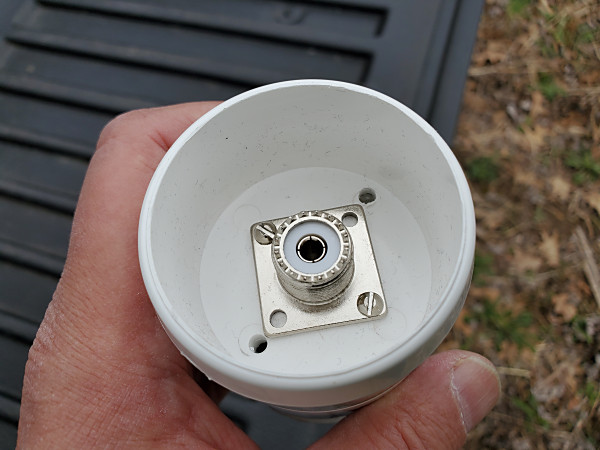
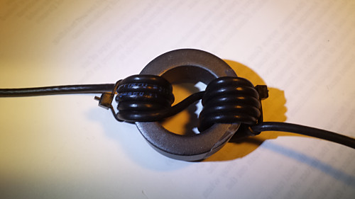
Sometime later, tried the same length wires with one of my homebrew 4:1 ununs. That time I used 20 feet of RG-316, and it loaded up fine on all bands.

The AD8HK winder/unun. The gray thing is a Velcro strap I used to secure it to the pole.
The AD8HK winder/unun secured to the pole with a Velcro strap.

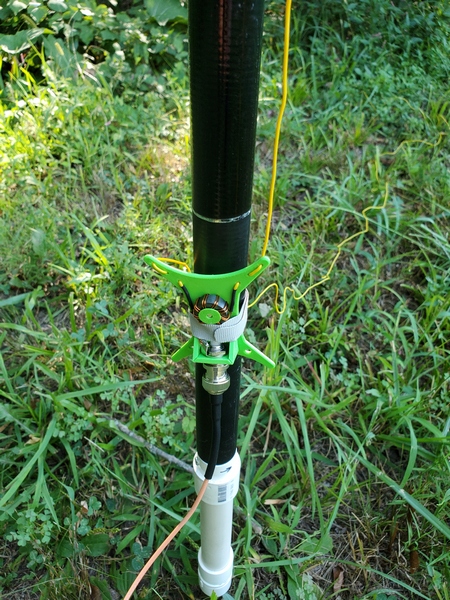
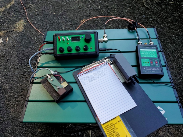
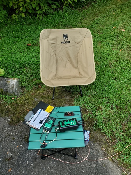
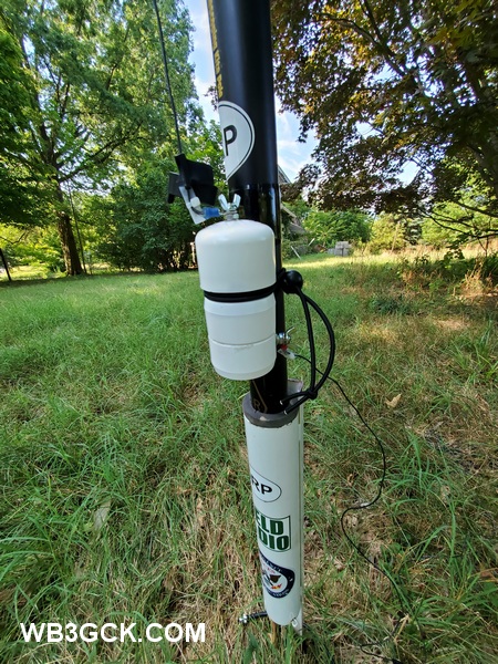
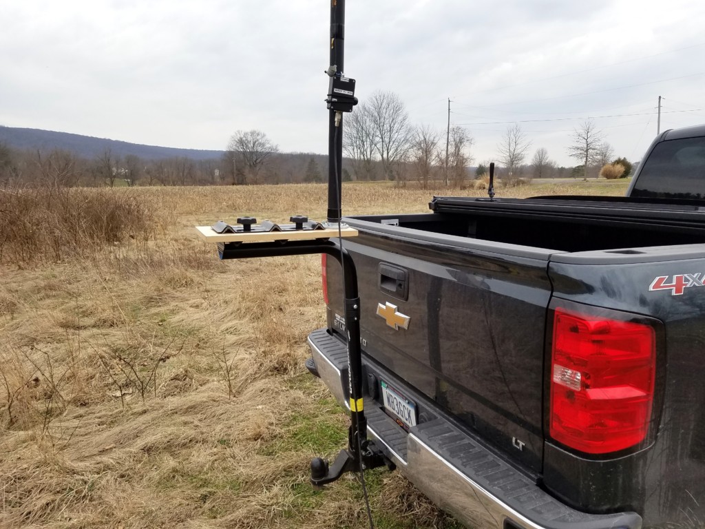
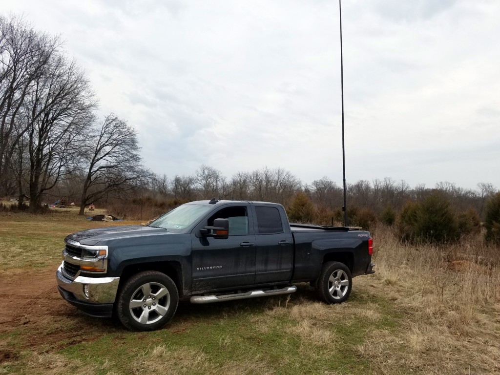
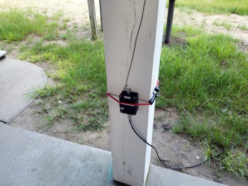
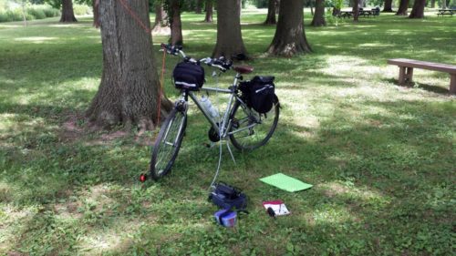
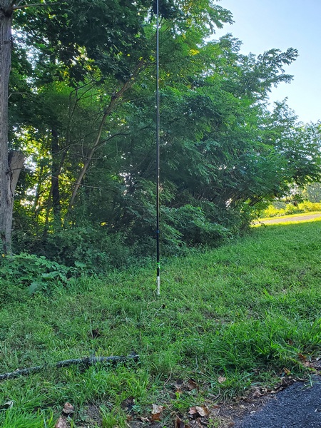
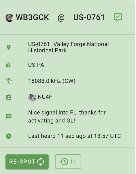
This morning I took the AD8HK EFRW over to Valley Forge National Historical Park (US-0761, KFF-0761) for an activation. I supported the antenna with a 20-foot pole and my homebrew ground mount. I fed the antenna with 20 feet of RG-316, and this time my T1 ATU easily found a match on 40M. It also loaded up fine on 30M through 17M. 

My antenna pole
My antenna pole

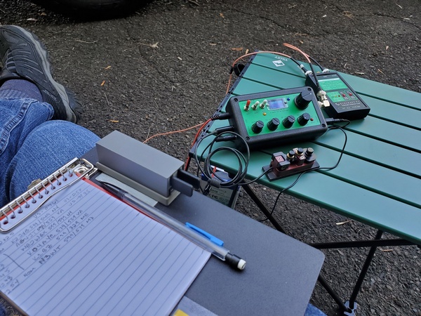
A 15-foot radiator isn’t going to be a barn burner on 40M; however, this little antenna certainly held its own today. I easily logged 13 contacts on 40M before moving on to try other bands. When I wrapped up after a little over an hour, I had twenty contacts in the log, with four park-to-park contacts. I made contacts on all four bands covered by my Penntek TR-35 (40M-17M), and I was pleased to work W6LEN out in California on 20M. 

My usual set up: Penntek TR-35 and Elecraft T1 ATU

After today, the AD8HK EFRW has definitely earned a spot in the KH1 kit I’m putting together. It’s easy to deploy and has a relatively small footprint. 

Thanks to NU4F for the nice spot from Florida

Speaking of my KH1… I heard from Elecraft a few days ago. They replaced the FET in the final amplifier, and now the rig is on its way home. I can’t wait to get it back on the air.

72, Craig WB3GCK

More Antenna Testing in Valley Forge

In my last post, I talked about using a simple antenna comprising a 15-foot radiator, a 7.5-foot counterpoise, and a 4:1 unun. It worked well, but I found it a little touchy to tune on 40M. Today, I tried the same configuration, but with a slightly longer radiator and counterpoise.

I wanted to add a little length to the radiator, but limit it to 19 feet, so I could still use my lightweight 19.5-foot telescoping pole to support it. Looking at a table of random wire antenna lengths to avoid, it seemed like 18 feet might be a good choice for 40M through 15M, my primary bands of interest. Scaling the counterpoise wire proportionately, I went with a length of 9 feet. 

Just as I was getting ready to cut a set of wires to try out, I stumbled on a video by Thomas K4SWL. In the video, he was using an antenna built by AD8HK that used a radiator length of 17’9” and a counterpoise length of 8’10.5”. I went with those dimensions, since they were very close to what I was considering and seemed to work with Thomas’s KH1.  

On the Air

To try it out, I made a quick trip over to Valley Forge National Historical Park (US-0761, KFF-0761). Using the same 4:1 unun and coax as the last time, I made a quick check to see how my Elecraft T1 loaded up on the bands. The tuner quickly found a match on 40M, 30M, 20M. On 17M, however, it seemed to struggle. I went back to 40M and got started with my activation. 

My radio equipment at Valley Forge NHP

This wasn’t the best day to be doing this. The geomagnetic field was unsettled with a K index of 4 and the A index sitting at 47. Nevertheless, the callers showed up, although at a somewhat slower pace than usual. 

After I had 14 contacts in the log, I decided to spend the rest of my limited time playing around with the antenna. When I went back and checked 17M, the T1 tuned it up without flinching. I also rearranged the counterpoise wire so it ran 180 degrees opposite of my coax. Checking the bands again, the T1 reliably matched 40M through 17M. 

My antenna at Valley Forge NHP

Convinced that the new wire lengths work, I went back to the 15-foot radiator and 7.5-foot counterpoise I used a few days earlier. This time, the T1 had no issues loading up on 40M. Go figure! 

I really wanted to give the unun with the smaller ferrite core another shot. When I last tried it with the 15-foot & 7.5-foot wires, neither my KH1 nor my T1 could find a match on 40M. Unfortunately, I neglected to put it in my backpack before I left. I’ll have to save that for another time. 

The Straight Key Century Club (SKCC) Weekend Sprintathon contest was going on this weekend, and I worked one SKCC station while tuning around the bands. This month, the WES theme was homebrew keys. In the spirit of the contest, I made the contact using a straight key I built a few years ago from junk box parts. 

My homebrew straight key constructed from odds and ends in my junk box
My homebrew straight key constructed from odds and ends from my junk box

Conclusions

So it looks like both the 15’/7.5’ and 17’9”/8’10.5” configurations are usable with my homebrew 4:1 unun. Given a choice, though, I would probably stick with the longer wires. 

One other thing is clear: short random wires can sometimes be finicky little critters.  When in doubt, rearrange the counterpoise wire.

72, Craig WB3GCK

Antenna Testing at Ridley Creek

On Wednesday, August 7th, I set out to do some antenna experimentation. So, why not get in a POTA/WWFF activation at the same time? To kill those two birds with one stone, I drove down to Ridley Creek State Park (US-1414, KFF-1414). (Disclaimer: No birds were actually harmed during this activation.)

I saw some discussion on the Internet about an antenna configuration I found intriguing. It’s just a 15-foot radiator and a 7.5-foot counterpoise wire fed through a 4:1 unun. Folks claim they work on 40M through 15M—with a tuner, of course. I’m a sucker for simple, field-expedient antennas, so I gave it a try during the recent Flight of the Bumblebees contest.

With the unun I used, I had mixed results. I couldn’t get the antenna to load on 40M, but it seemed to do fine on 30M through 15M. I wanted to try the same configuration, but with a larger 4:1 unun I built a several years ago. After cutting another set of 15-foot and 7.5-foot wires, I was ready to go.

My antenna feedpoint

When I got to the park, I headed to a spot I had been using a lot lately. It’s off the beaten path and well away from the other park visitors. Using my homebrew ground mount, I set up the antenna on a lightweight 19-ft telescoping pole I bought years ago on eBay. I ran 20 feet of RG-316 coax over to my Penntek TR-35 and Elecraft T1 tuner. 

My operating position at Ridley Creek State Park
My operating position

Before I started my activation, I gave the antenna a quick check. The antenna was an easy match on 30M through 17M, but it took two tries before the T1 found a good match on 40M. 

Despite the slightly fussy tuning on 40M, the antenna didn’t do too badly on that band. I logged 12 contacts before the activity slowed down. I next tried 30M, but there were no takers. Moving up to 20M, I logged three more stations. Up on 17M, I worked one last station in Alabama. After an hour on the air, I had 16 stations in the log, including five park-to-park contacts. 

Selfie at Ridley Creek State Park with my antenna in the background
Something in the woods behind me was not happy with my presence. Fortunately, I never came face-to-face with whatever it was.

I had better luck with this antenna configuration this time around. The unun I used for this outing uses a larger iron powder toroid (T130-2, as I recall) compared to the smaller ferrite core used in the other unun. Also, the longer run of coax I used this time was probably a contributing factor. 

In any event, this configuration can definitely work. Granted, it’s a compromise antenna, but it’s super simple to deploy for casual operating in the field. Still, I think a slightly longer radiator would make for an easier match on 40M. 

I have another configuration in mind that I plan to try soon.

72, Craig WB3GCK

Portable 4:1 UNUN

I recently came across a product on Etsy that caught my eye. It’s a 3D printed project box with an integrated antenna wire winder. I couldn’t resist, so I ordered one.

The Etsy vendor is 3dPrintedSolution, and they list the product as “EFHW End Fed Half Wave Antenna Radio Box.” While its name suggests they designed it with EFHW antennas in mind, I had a slightly different plan for it. 

The box will accommodate a T-130 toroid, and the snap-on lid comes with a gasket. There is a pre-drilled hole for a BNC-F panel mount connector, and there are marks to guide drilling for the output and ground connectors of your choice. You can choose from two colors: orange or green. The vendor states that it is “UV and weather resistant.”

I like the idea of having a box to enclose the balun or transformer. My preference for portable antennas is to avoid exposed components or circuit boards. 

I used mine to build a 4:1 unun for portable use in a Rybakov configuration. The unun consists of 19 bifilar turns of #24 solid hookup wire on a T130-2 toroid. You can find plans for winding the unun here and other places on the Internet. For the output and ground connections, I used #10-24×3/4″ stainless steel machine screws, along with some nuts, flat washers, and lock washers. 

Inside view of the 4:1 unun. I used double-sided foam mounting tape to secure the toroid. I also use a small piece of packing foam (not shown) between the lid and the toroid for added stability.

To go along with the completed unun, I prepared two 26-foot wires; one for the radiator and one for a counterpoise. I finished up by attaching a length of 2.5mm bungee cord. This cord keeps everything together for travel. I have also used it to secure the box to a vertical support, e.g., fiberglass mast, fence post, etc. 

The 4:1 unun deployed in a Rybakov vertical configuration with a 26-foot radiator and a 26-foot counterpoise

In the field, this Rybakov antenna worked as well as others I have built over the years. I tested it using my Penntek TR-35 and Elecraft T1 tuner with 18 feet of coax. It tuned up easily on 40, 30, 20, and 17 meters, and I made a couple of QSOs while testing. The integrated winder made it easy to deploy and take down. 

The 4:1 unun packed up for travel

I have a feeling another one of these boxes is in my future. Maybe a 9:1 unun next time?

73, Craig WB3GCK

Weather-Resistant 4:1 UNUN

One antenna I plan to try during my annual Outer Banks, North Carolina, vacation this summer requires a 4:1 unun. If the antenna works as hoped, it’ll be in place for the entire week. So, I need an unun that can stand up to the elements.

About a year ago, I built a 9:1 unun in a weather-resistant housing made from PVC pipe parts. I had some parts left over from that project, so I built a 4:1 unun version. The construction of this unun is like the last one, however, this one has a ground terminal.

Weather-resistant 4:1 unun components

I wouldn’t want to take this unun on a backpacking trip; it weighs in at a substantial 8.6 ounces. When I’m going to be operating from a location for an extended period, however, this should do the trick. 

Parts

The parts for the housing are similar to the last one, but there are some additions for the ground connection.

  • About 2.5 inches of 1.5-inch PVC pipe
  • (1) 1.5-inch PVC end cap (slightly rounded top)
  • (2) 1.5-inch PVC end caps with flat tops
  • (1) SO-239 panel-mount connector (along with some #4 hardware for mounting)
  • A 4:1 unun wound on a T130-2 toroid
  • (2) #10-24×3/4″ stainless steel machine screw (along with some #10 flat washers, nuts, wing nuts, and lock washer)

The PVC end-caps with flat tops can be hard to find. If you search online for furniture-grade end caps, you might find some. 

Construction

You can find plans for winding the unun here and other places on the Internet. The one I built for this project uses 19 bifilar windings of #24 solid hookup wire on the T130-2 toroid. 

To start, you need to glue the two flat top end caps together. When dry, drill the holes to mount an SO-239 connector in the center. 

The underside of the 4:1 unun. The SO-239 is recessed to provide some protection from the elements.

For mechanical reasons, I added the #10-24 stainless steel screw for a ground terminal in the lower half of the connector housing. A short length of wire runs from the ground screw through a small hole and connects to one of the SO-239’s mounting screws. I installed another #10-24 screw in the slightly rounded end cap for the antenna connection.

The final assembly was straight forward. I soldered the toroid’s input wires to the center pin of the SO-239 connector. Then, I attached the toroid’s ground wire to one of the SO-239’s mounting screws. 

This is how the toroid is installed in the Weather-Resistant 4:1 UNUN.

Next, I inserted the PVC pipe section into the connector housing. I then installed a ring lug on the output wire. I left the output wire just long enough to make the connection to the output bolt in the rounded end cap. Before mounting the end cap to the PVC pipe, I added some pieces of foam around the toroid core to hold it in place. Then I press-fitted all the PVC parts together.

Testing in the Field

I tested the 4:1 unun in the field recently, and it performed as expected. I used it as part of a Rybakov vertical, with a 26-foot radiator supported by a Jackite pole, another 26-foot wire on the ground for a counterpoise, and 18 feet of RG-8x coax. My little Elecraft T1 tuner matched it with no problems on 40M, 30M, 20M and 17M, the bands covered by the rig I was using. Similar 4:1 ununs I have built worked well from 40M through 6M, so I’m confident this one will, too. While I was testing, I had a couple of nice CW rag chews on 40M and 30M. 

The weather-resistant 4:1 unun in use. In this configuration, there's a 26-foot radiator and a 26-foot counterpoise wire.
The weather-resistant 4:1 unun in use. In this configuration, there’s a 26-foot radiator and a 26-foot counterpoise wire.

Wrap-up

Like its 9:1 counterpart, this unun is probably a bit over-engineered. My weather-resistant 9:1 has served me well through several camping trips and two Field Days, so I expect this 4:1 version will do likewise. So, bring on that beach weather!

73, Craig WB3GCK

Weather-Resistant UnUn

When camping or on vacation, one of my go-to antennas is a simple 29.5-foot wire and 9:1 unun. In these situations, the antenna is usually up for days, and I have to use plastic shopping bags to protect the unun from the elements. For this project, I attempted to build an unun that can withstand the elements.

I had been thinking about this for a while. I wanted something that would protect the internal parts and provide some protection for the coax connection. Eventually, my stash of PVC pipe odds and ends caught my attention. I figured if this stuff could keep water in, it should be able to keep water out. What I came up with is somewhat weird-looking, but it should do the job

This is the completed 9:1 UnUn.

Parts

Here are the major parts I used:

  • About 2.5 inches of 1.5-inch PVC pipe
  • (1) 1.5-inch PVC end cap (slightly rounded top)
  • (2) 1.5-inch PVC end caps with flat tops
  • (1) SO-239 panel-mount connector (along with some #4 hardware for mounting)
  • A 9:1 unun wound on a T130-2 toroid
  • (1) 10-24×3/4″ stainless steel screw (along with some #10 flat washers, nuts, wingnut, and lock washer)

I have to mention a few things about the parts. The PVC end-caps with flat tops are hard to find. If you search online for furniture-grade end caps, you might find some. For winding the toroid, the Emergency Amateur Radio Club in Hawaii (EARCHI) has excellent instructions you can download. 

Construction

I wasn’t sure how I was going to put this together until I started building it. So, these won’t be detailed, step-by-step instructions. They should, however, give you a general idea of how I ended up assembling it. 

  • First, I glued the two flat end caps together, end-to-end. 
  • While the glue was drying, I wound the unun. I left the leads a little longer than the EARCHI instructions, but I cut them back as needed during assembly. I used some #22 gauge solid hookup wire for the windings.
  • I drilled a 5/8-inch hole through the two attached end caps and installed the SO-239 connector. To keep things simple, I only used two screws to mount it. So, I only drilled two holes for the #4 machine screws for mounting. I also created a couple of weep holes to allow any condensation to drain out. I don’t know if these are needed or not, but they won’t hurt. 
  • I drilled a hole in the rounded end cap for the #10 screw. I made this hole a snug fit for the screw.
  • Next, I soldered the toroid input and ground connections to the SO-239. I left the toroid leads about 1.5 inches long. I used a small lug to attach the gound lead to one of the SO-239 mounting screws.
  • I then soldered a ring lug onto the end of the output wire (antenna connection) and attached it to the stainless steel bolt. I made sure that this output lead was just long enough to make the connection to the bolt. (You probably noticed a splice in this wire. I cut it by mistake, while installing the toroid. Stuff happens!)
  • I squeezed in some foam packing material on both sides of the toroid to hold it in place.
  • Finally, I press-fitted the top end cap. The end caps are on pretty tight, so I decided not to glue the parts together. With a little effort, I can still get inside of it if needed.
This is a view of the toroid. Before I closed it up, I wedged pieces of packing foam on either side of the toroid to hold it in place.

I don’t typically use radials with this setup, so I didn’t provide for an external ground connection. I rely on the coax shield for the necessary counterpoise. Should I ever need to, I can easily add a ground stud. 

This is a view of the bottom of the UnUn. I added two "weep holes," in case there's any condenstation inside. These probably aren't necessary.
This is a view of the bottom of the UnUn. I added two “weep holes,” in case there’s ever any condensation inside. These probably aren’t necessary.

Field Testing

I took the unun out for a test drive, and it performed as expected. With a 29.5-foot radiator and 25 feet of RG-8x coax, the internal tuner in my KX3 was able to load it up from 80M through 6M.  (This type of antenna is certainly compromised on 80M and 60M, but I have made lots of contacts with them.)

This is the weather-resistant unun in use. I used an adjustable bungee cord to strap it to the Jackite pole. The recessed connector helps to protect the coax connection from the elements.

The Straight Key Century Club (SKCC) Weekend Sprintathon (WES) was in progress while I was out, so I made a few contest contacts. Running my usual 5 watts, I worked two French stations on 20M. I was also pleasantly surprised to have a station in Hawaii come back to my 5-watt CQ on 15M. So, it looks like it’s working. 

I also inadvertently tested the unun’s mechanical integrity. I accidentally dropped it twice before using it for the first time. No problems.

Conclusion

I admit I might have over-engineered this thing, but it was a fun project, nonetheless. Our first camping trip of the season is two weeks away. Hopefully, we won’t have any rain. But, if we do, my antenna will be ready for it.

73, Craig WB3GCK

Bike Rack Vertical

[This is an updated version of a post that appears on my old website. – WB3GCK]

I do quite a bit of my QRP operating from portable locations. I like to use simple wire antennas but, truth be told, I really dislike spending my limited operating time trying to get antenna wires up into trees.  Also, when activating parks for Parks on the Air (POTA), I often operate from the cab of my truck and need an antenna that is self-contained and quick to deploy.  This set up fits the bill.

What I did was modify my homebrew roll-on mast support so I could use my hitch-mounted bicycle rack to support it. This only required the drilling of two holes in the roll-on mount. Figure 1 shows the roll-on mount clamped into the bike rack. In this case, I was supporting a 31-foot Jackite pole. After extending the pole and removing the bottom cap, I just lower the pole onto the 1-1/4 inch pipe. That’s all there is to it.

Bike Rack Antenna Mount. A 9:1 unun is attached to the Jackite pole with a bungee cord.

By selecting the right size of pipe, I can use this technique to support a variety of masts. For example, I’ve used this type of mount to support two 5-foot sections of TV antenna mast. I used this configuration to support a 1.2 GHz yagi for DStar digital communications during an ARES-RACES drill years back.

My new truck's first QRP-portable outing.
The Bike Rack Vertical in use

When operating QRP-portable, I often use a vertical antenna made from a 30-foot piece of hook-up wire and fed through a homebrew 9:1 unun with an 18-foot length of RG-8x coax. The unun is just attached to the 31-foot Jackite pole using some small bungee cords. No radials are used, which gives this set-up virtually a zero footprint. You can find more information on this configuration on the EARCHI website. I’ve successfully used this antenna in the field over the past few years. It’s a bit of a compromise, as antennas go, but it has always served me well. The extra height using the bike rack mount seems to help performance a bit. (Although I can’t quantify that, I’m sure the extra height doesn’t hurt.) With the internal antenna tuner in my KX3, I can work all bands from 40 through 10 meters.  Heck, I’ve even used it on 80 meters a bunch of times.

I used this particular antenna configuration countless times in recent years.  It was my “go to” antenna for NPOTA activations.  Within 5 minutes of arrival, I can be on the air. When it’s time to leave, tear down is just as fast. Now, that’s what I’m talkin’ about!

73, Craig WB3GCK

Outer Banks 2017

For our annual vacation this year, our extended family rented a house in the town of Corolla on the Outer Banks of North Carolina. Of course, ham radio was a part of my week’s activities.

I’ve operated my QRP equipment from numerous beach houses over the past 20 years but this year highlighted the need to be flexible and adapt. Before I left for vacation, I looked at some pictures of the house online and did some aerial reconnaissance (Google Earth) to see where I might set up my radio and antenna.

I initially set up a 30-foot vertical on a 3rd-floor balcony on the front of the house. I ran my coax down to an unused bedroom on the 1st floor. That was a great place to operate but the noise levels were horrendous. My vertical was a bit too close to some electronics (TVs, WiFi equipment, etc.). I made one contact before taking down the antenna and moving on to Plan B.

After studying the back of the house (furthest away from all of the electronic gadgets), I decided to go with a 53-foot wire in an inverted L configuration. I ran the wire vertically along a wooden deck up to the 3rd floor. From there, I ran the wire out horizontally to a Jackite pole strapped to a volley ball net. The last 6 feet or so of wire ran back down the Jackite pole. So, I guess it was technically an “inverted J.” Whatever you want to call it, it served me well. I still had some intermittent noise issues but it was more manageable than before.

This is a view of the rear of the house showing how I supported my inverted L. The wire ran up the side of the deck and out to the Jackite pole strapped to the volley ball net. The last 6 feet or so ran down the Jackite pole. So, technically, it was more of an inverted "J" than an "L."
This is a view of the rear of the house showing how I supported my inverted L. The wire ran up the side of the deck and out to the Jackite pole strapped to the volley ball net. The last 6 feet or so ran down the Jackite pole. So, technically, it was more of an inverted “J” than an “L.”

I fed the antenna through a 9:1 unun with an 18-foot run of coax going in through a nearby window. My KX3 was wedged into the corner of a ground floor bedroom.

This is a homebrew 9:1 unun at the feedpoint of my antenna. The wire went up vertically about 23-feet before extending out horizontally to the Jackite pole.

On the air, this impromptu antenna worked surprisingly well. It was especially effective on 40 and 30 meters. If I ever get bored enough someday, I might model it to see what it looks like on paper.

My “cozy” operating position next to a foosball table. If you look carefully, you can see the 9:1 unun through the window.

The bands were pretty flakey this week but I managed to make contacts every day. I fell into the pattern of getting on 40 meter CW early in the morning then doing some PSK-31 on 40 meters in the evening. I had some nice CW rag chews and worked some Carribean and South American DX on 40M PSK-31.

One notable highlight was working Joe N2CX who was doing Parks on the Air (POTA) activations in Canada. Despite the lousy band conditions, I worked him at three different parks. I worked two of the parks on two bands and one of them on three bands.

We had some thunderstorms and heavy rain on our last day there, so I took the antenna down and packed up the radio stuff a little earlier than I wanted to.

It was a fun week in North Carolina and we’re already looking at houses for next year. You can bet that I’ll be ready with several antenna options. You just never know what to expect.

72, Craig WB3GCK

Save

Save

Holiday Weekend Bike Ride

For a long, holiday weekend, it’s been pretty busy around here.  I managed to get in a bike ride this morning on the nearby Perkiomen Trail.

On my way back to the trailhead, I stopped for a brief QRP session.  I tossed a line up over an opportune branch and hoisted up a 29.5-foot wire.  It wasn’t the highest branch but it let me operate under a shady tree.  I laid another 29.5-foot wire out on the ground for a counterpoise.  I’ve had very good success with this configuration on many occasions, while feeding it through a 4:1 unun.  Today, I tried attaching the wires directly to my KX3 using a BNC-to-binding post adapter.  The KX3 managed to tune it with an SWR less than 2:1 on 40 and 30 meters.  On 20 meters, however, I couldn’t get it below 5:1.  So, I quickly hooked up the 4:1 unun and about 6 feet of coax.

Once again, I pressed my bike into service as an antenna support. One handlebar grip has a 4:1 unun attached to it. The other grip is where I tied off the line used to hoist the antenna.

Not hearing much activity on 20 meters, I tuned around 30 meters and heard W9CBT calling CQ from the Chicago area.  The QSB was bad and we just couldn’t complete the QSO.

My station setup today. The food storage container houses LiFePO4 battery.

Down on 40 meters, I had a quick exchange with K2D in Connecticut, one of the 13 Colonies special event stations.  I called CQ on 7.030 and wound up having a nice two-way QRP QSO with John, W3FSA, in Portland, Maine.  We managed to hang in there despite some deep fading at times.

After that, I quickly packed up and rode the last few miles back to the trailhead.  The weather was perfect and I would have liked to stay longer.  However, I needed to get home to put some ribs on the smoker.  I have my priorities in order!

I wish all of my U.S. ham friends a happy and safe 4th of July.

72, Craig WB3GCK

Line Isolator

One of my favorite portable antennas is a 30-ft wire fed through a 9:1 unun.  This type of antenna generally the uses coax feeder as a counterpoise, since the 9:1 unun configuration provides no line isolation.  Most of the time, this has worked well for me with no issues with stray RF getting back into the equipment.

On a couple of occasions, my Elecraft T1 auto tuner began to act up, refusing to load up on one or more bands. (Running through the T1’s diagnostic mode always seems to restore operation to normal.)  I’ve also had one of my keyers behave erratically once or twice.  Since this has only happened when using the 9:1 unun, my suspicion is that common-mode RF currents on the coax shield are the culprit.

My proposed solution for this is to use a line isolator between the tuner and the coax feeder.  (Note:  Using a line isolator at the antenna end of the coax would defeat the purpose in using the coax as a counterpoise.)  A quick survey of my junk box stash of parts showed I had everything I need to build a line isolator from scratch.

Parts List

  • RG-174/U coax (approximately 24 inches)
  • FT-140-43 ferrite core
  • (2) BNC-F chassis mount connectors
  • Hammond Manufacturing 1591MSBK Enclosure (2.2 x 3.3 x 0.8 inches)

Construction

This is a very simple project.  You can build one in well under an hour.

  • The RG-174 coax is wound on the FT-140-43 core for a total of 10 turns.  Take note of how the 5th turn goes across the core.  This makes installation in the case a little easier.  I used a couple of small nylon tie-wraps to hold the windings in place.
  • Drill the holes for each of the BNC connectors and wired up the choke, as shown.  I used a 5/64-inch drill bit and had to use a reamer to get the holes to the right size for the BNC connectors I used.
  • Solder the coax to the BNC connectors.
  • To mechanically secure the core, I used a piece of two-sided foam mounting tape to mount the choke to the bottom of the case.  As an additional precaution, I put a piece of packing foam on top of the choke before attaching the lid.  This foam provides a slight downward pressure on the choke to prevent it from shaking loose in the case during handling.

line_isolator_core
Core winding

isolator_core_installed
Core installed in case

Testing

I don’t have access to the equipment necessary to do any type of exhaustive testing of the line isolator.  In lieu of that, I hooked it up to a 50-ohm dummy load and checked the SWR.  It was basically flat from 160M through 6M.  While that tells me nothing about how effective it is in reducing common-mode currents, I at least know I didn’t make any serious screw-ups in building it.

2015-11-08 13.45.50
Completed line isolator

In Operation

Well, this part will have to wait until I have a chance to get out for some portable operating.  I want to make sure that the line isolator doesn’t affect the T1’s ability to tune my antenna.  Since the initial problems were very intermittent, only time will tell if I solved those problems or not.  I’ll be sure to update this post with any new insights I gain.

Update 5/16/2017:

Since this article seems to get a lot of traffic, I figured it was time for a long-overdue update.  Not long after this post was published, I tested this 1:1 unun in line with the coax to my 30-foot wire and 9:1 unun.  As I suspected it might, it affected the tuning of the antenna.  One or two bands wouldn’t load up properly.  This made sense to me, since this antenna configuration relies on the shield of the coax for the counterpoise.  So, there’s some RF on the coax shield by design.  This device obviously is blocking some RF, as it should.  I haven’t pursued it further and I still have done any measurements to determine its effectiveness.  With a change of connectors on the output side, it could definitely be useful as a 1:1 balun, I suppose.

Save