On one of the several ham radio mailing lists I subscribe to, there was some recent discussion about unusual antennas. You know—bed springs, light bulbs, and the like. It brought to mind a memorable QSO I had 27 years ago.
In the July 1993 issue of QST, Rod Newkirk W9BRD (later VA3ZBB, now SK) wrote an article about building small, multi-turn loop antennas[1]. If his name doesn’t ring a bell for you, Rod wrote the “How’s DX?” column in QST from 1947 to 1978 and coined the term, “Elmer.”
Although I never actually built one of Rod’s loops, I found the article fascinating. At the end of the article, Rod noted that he conducted his loop antenna experiments in the partially-underground cellar of his Chicago home. Remarkable!
Fast-forward to September 1993. I went downstairs to my basement shack one evening and fired up my old MFJ-9030 on 30M CW. I had three QSOs that night; one of them was with—you guessed it—W9BRD.
During our QSO, Rod mentioned that he was using one of his experimental mini-loops indoors in his shack. When I told him I was running 5 watts into my rainspout, he sent back, “Hey, if it’s metal, load it up.” According to my log, we chatted for about 12 minutes before signing.
Needless to say, that contact put a smile on my face. It was the kind of QSO I really enjoy—one with a station using an unusual set-up or operating in a unique location. I guess you could say this QSO checked both of those boxes. Not to mention that I had just worked a very well-known figure in Amateur Radio.
QSL card from W9BRD documenting our unusual QSO in 1993.
I fired off a QSL card to Rod to acknowledge our QSO and to let him know that I enjoyed his loop article. Before too long, I received a card back from Rod. His typewritten note on the back of the card continued the theme of our QSO. It read, in part: “Hey, if your XYL uses gold or silver thread for that needlepoint, let’s try loading it up, Craig.” He also wrote about his experiences with rainspout antennas, including his attempt to feed a particularly stubborn one.
Rear of W9BRD’s QSL card
From articles I have read, it’s clear that Rod had a penchant for assembling and experimenting with unusual antennas. His daughter, Amanda, once wrote: “He especially loved discovering how much of a signal he could achieve with his various objects: the coffee cans, cookie tins, piles of wire and boxes and tidbits—out of which he wrung quite magical things.”[2]
When it comes to unusual antennas, Rod was a man after my own heart. Over the past 27 years, his words from our QSO have been my mantra: “If it’s metal, load it up!”
Thanks for the inspiration, Rod.
73, Craig WB3GCK
References: [1] Newkirk (W9BRD), Rod. “Honey, I Shrunk the Antenna.” QST, July 1993, pp. 34-35, 39. [2] Newkirk (WN9PMC), Amanda. “On Being W9BRD’s Daughter.” K9YA Telegraph, Vol 11, Issue 9, September 2014, pp. 2-3. (K9YA Telegraph website)
I’ve been intrigued by the half-square antenna for some time now. I don’t have the real estate to put one up at home, so I built one for portable use. Like my other speaker wire projects, this antenna is built from a 50-foot length of cheap, two-conductor wire.
You can think of the half-square as two quarter-wave verticals spaced a half-wavelength apart. It provides some gain over a quarter-wave vertical and has a low take-off angle. The half-square has a bi-directional pattern with lobes broadside to the antenna and nulls off of the ends.
Normally, the half-square is fed with coax at the top of one of the vertical elements and functions as a single-band antenna. The coax should be kept perpendicular to the vertical leg, to avoid interaction. That arrangement, however, would be somewhat awkward for a portable antenna.
For expediency in the field, I went in a different direction. I decided to feed it at the bottom of one of the vertical legs, which is a high impedance point. I use a 9:1 unun to reduce the high input impedance to something easier for a tuner to handle.
I designed this antenna for the 20M band, but I wanted to use it on other bands as well. By using the 9:1 unun to feed the bottom of the antenna, I’m able to squeeze some more bands out of it. A tuner is required, of course.
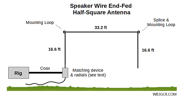
Refer to the accompanying diagram to help make sense of the following steps.
Separate the speaker wire into two 50-ft wires
On one of the wires, install a spade lug at one end. This will be the connection to your matching device)
From the spade lug, measure up 16′ 7.2″ and make a small loop using two small zip-ties.
From the second wire, cut a length that is about 16′ 9″ or so.
Strip and splice the smaller wire to the end of the larger wire. After soldering it, I covered the splice with heat-shrink tubing.
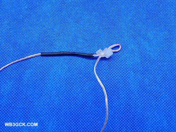
Next to the splice, make another small loop, using two zip-ties.
At the end of that wire, twist the wire to form an attachment loop. When you do this, make sure you have 16′ 7.2″ from the splice to the attachment loop.
I applied some Goop® adhesive to the loop at the end of the wire to hold it together. I also added Goop® to each of the other attachment loops.
As is my usual practice, I added some Goop® to where the wire enters the spade lug to add some strain relief.
At this point, the antenna is finished. You can, however, cut the leftover wire in half to make two radials for 20M (approximately 16 feet, give or take). I installed a spade lug on each of these wires and twisted the other ends to make a small loop. You guessed it; I put Goop® on these wires, as well.
This photo shows the splice and one of the mounting loops used in the Speaker Wire Half-Square.
Matching
[Update (6/17/2020) – After initially publishing this post, I received some great feedback from readers. As a result, I have updated, clarified, and expanded this section.]
For my first couple of outings with this antenna, I used a 9:1 unun as a quick and dirty way to get it on the air. I run about 18 feet of RG-8x coax from the unun to the radio. There’s nothing particularly critical about the coax length, but I would recommend a minimum of 16-feet for 40M and up. The exact length of the radials isn’t critical either since they’re laying on the ground. In fact, you can probably use the antenna without them. In this case, you’re relying on the coax shield for the counterpoise.
While the 9:1 worked fine, there are more efficient ways to match this antenna. I plan to continue experimenting with other methods to match the high-impedance input on 40M and 20M.
I haven’t tested them myself, but the end-fed halfwave tuners from Pacific Antenna and QRPGuys should work on 20M and 40M. They use a parallel resonant circuit and are designed to match an end-fed halfwave (EFHW) antenna.
An EFHW transformer, like the ubiquitous 49:1 transformer, should also work. You will likely need to do some pruning on the antenna to get the SWR where you want it.
Finally, a simple L-Match antenna tuner with a tapped inductor in series and a variable capacitor across the output looks like it may be the best solution for me. It should handle the high impedances on 40M and 20M, and work on other bands like a random wire tuner. This will definitely be part of my next round of experiments.
Deployment
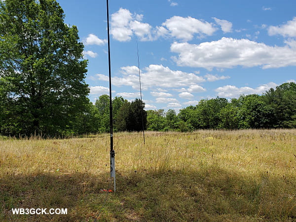
Deploying this antenna is a snap and takes me about 5 minutes. I use two collapsible poles to support it. I attach one corner to a partially-extended 28-foot Jackite pole. The feed point of the antenna is about 3 feet off the ground.
These are the two poles I used to support the Speaker Wire Half-Square. Unfortunately, the wire is too thin to be visible in this picture.
I use a 20-foot Black Widow pole (actual length about 19.5 feet) to support the other end. I support this pole with an appropriately-sized screwdriver shoved in the ground. The handle of the screwdriver fits snugly inside the bottom section of the pole. After attaching the other corner of the antenna to top of this pole, I extend the pole and remove the bottom cap. Next, I walk the pole back until the horizontal section is taut. Then, I just shove the screwdriver in the ground and place the pole over it.
With appropriate trees nearby, you might be able to eliminate one or both of the poles. I’m not usually that lucky.
Results of Field Testing
I was pleased with the results of my initial field tests with the half-square. The internal tuner in my Elecraft KX3 was able to load the antenna from 80M through 6M. (Since the antenna’s input impedance is low on 80M, I wouldn’t recommend using the 9:1 there.) The SWR was 1.2:1 or better on all bands with the tuner.
During my first outing with the half-square, I was able to make contacts on 40M, 20M, and 15M at 5 watts with no difficulty. The antenna is a half-wavelength on 40M, and it appears to play well on that band. I had numerous Reverse Beacon Network spots on 40M showing a signal-to-noise of 20db or better.
I also used it in the field during a recent QRP contest with similar results. Signals were strong on 40M, and I worked Georgia and Quebec on 20M.
This was hardly a rigorous scientific evaluation, but I’m happy with this antenna so far. One of these days, I’d like to do some modeling to see what the radiation patterns look like on the various bands. In the meantime, I’ll do some more experimenting with impedance matching.
Wrap-Up
This was an easy and fun project. It certainly made good use of a roll of cheap speaker wire. After using this antenna in the field a couple times, I have officially added it to my arsenal of portable antenna options.
Like many of you around the world, I’m under a stay-at-home order, due to the pandemic. Taking advantage of my new-found spare time, I decided to take care of some overdue antenna maintenance.
I’ve been using my rainspout as my main antenna at home since 1993. It’s a compromise antenna, but it has given me a way to get on the air from my real estate-challenged home. Normally, I do some routine maintenance on it annually, but I’ve been lax lately. It’s been about two years or more since I’ve cleaned up the connections. This was the perfect time to get caught up.
My normal maintenance routine is to re-do the connections at the downspout. The connections are subject to exposure to the elements on the outside and rainwater coming down the inside. The downspout is on a south-facing side of the house, so the sealant on the connections also takes a beating from the sun.
Sometimes, my maintenance reminder is when I notice a change in antenna performance. Typically, it’s a change in the tuning. I might notice, for example, problems loading up on one or more bands. This time, it was an increase in noise levels.
So, I headed out to the downspout and removed the screws I use to make the connection. I had to scrape off enough of the sealant I use to get a screwdriver in there. Next, I took some light sandpaper and sanded around the connection points. A few times over the years, I drilled new holes for the connections. This time, I just needed to clean things up a bit.
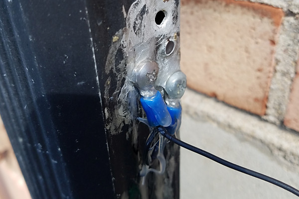
I use two ring lugs, jumpered together, to make the connections (see photo). My rationale is that two connections are better than one. If needed, I replace the ring lugs and the screws, but this time, they were still in good shape. I just cleaned them up a bit and reinstalled them. I finished up by resealing everything with a generous amount of Goop® sealant/adhesive.
This is the connection to the downspout. Two ring terminals, jumpered together, are used to ensure a good connection. I used a liberal application of Goop sealant to weather-proof the connections. (A second coat was applied after this picture was taken.) You can see some holes from previous connections. (Note to Self: Do some touch up painting on the downspout!)
Next, I moved indoors and turned my attention to the ground connections.
I have a 1/2-inch copper pipe that I use as a ground bus for my station. The pipe runs across the back of my radio desk to an incoming cold water pipe about 6 feet away. I use hose clamps and braided strap to make the connections to it. The 1:1 unun that feeds the wire out to the downspout is also grounded to the pipe with a braided strap and a hose clamp. The pipe itself is connected to the incoming water pipe with hose clamps and a short braided strap.
I couldn’t remember the last time I cleaned up these connections, so, it was time to get busy. I removed the connections to the copper pipe ground bus and cleaned up the pipe with light sandpaper and steel wool. I reinstalled everything, making sure the connections were tight.
Turning on my transceiver, I was pleasantly surprised with the fruits of my efforts. My local noise levels have always been high, and 40M has been the worst lately. The noise was S5 or S6 at times, but now it was down to S1 or S2. The noise on 80M was also an S unit or two lower.
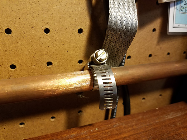
One of the ground connections at the operating position. The braid strap goes to the ground terminal on my 1:1 unun. The other end of the copper pipe ground bus uses hose clamps and a short piece of braid to connect to the cold water pipe coming into the house.
I wish I had taken care of this maintenance sooner. Next time, I’ll try not to procrastinate.
Stay safe in these difficult times. I’ll see you on the air.
Here’s an example of what can happen when you have a hunk of cheap wire and a little too much time on your hands.
Years back, I did a write-up on a simple, random wire antenna made from a 50-foot roll of speaker wire from a local dollar store. I nick-named it the Dollar Store Special. I had a similar roll of wire in my junk box, so I set out to see if I could build another useful portable antenna from it.
This time out, I wanted to build something more elaborate than a random wire. After some sketching with a pencil and paper, I came up with this simple portable delta loop.
There are certainly better ways to construct a delta loop. However, I just wanted to see if I could build a functional antenna using only cheap speaker wire. So, with that in mind, here’s how I did it.
The Design
The antenna I built was inspired by a portable delta loop designed by Doug DeMaw, W1FB. [1] Doug’s multiband delta loop was designed for the 40M band and used a 300-ohm balanced feeder.
According to Doug’s book, this type of antenna should work well on the fundamental frequency and higher. For the next band below the fundamental, he suggests connecting the feeder wires together and using it like a random wire. I figured I’d just try loading it up as is to see what happens.
Given that I constrained myself to a 50-foot roll of speak wire, I scaled my antenna for the 20M band. Using the formula, 1005 divided by the frequency in megahertz, I calculated a total length of 71 feet (21.6 meters) for the center of the 20M band. That would leave some of the two-conductor wire for an improvised balanced feeder.
Feeding the delta loop in a corner (with the apex of the loop pointing up), gives the antenna vertical polarity with a low take-off angle.[2] As with most antennas, higher is better. However, this antenna is still quite useful at practical heights in the field.
Since a tuner will always be necessary, I expended no effort trying to optimize the design.
Construction
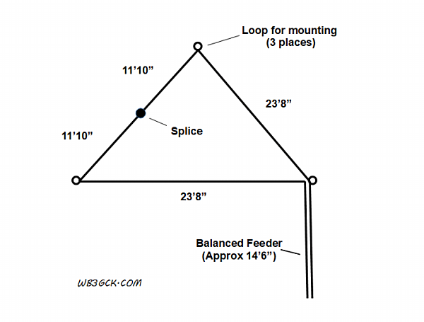
Schematic diagram of the delta loop antenna
If you’re a visual person like me, refer to the diagram to help make sense of the directions below.
Measure off 35.5 feet from one end of the speaker wire. Place a small zip-tie around the wire at this point.
Separate the 35.5-foot end of the speaker wire into two separate wires.
Strip and solder the loose ends of the 35.5-foot wires together. Put some electrical tape or shrink tubing over the splice.
Make 3 small loops in the wire, as shown in the diagram. You can see an example in the accompanying photo. These are going to be the attachment points. I used some Goop® adhesive on the zip-ties to help hold things in place.
Finally, install some spade terminals on the ends of the shorter conductors. These will be used to attach the antenna to your tuner or balun.
Example attachment point. This is the feedpoint of the antenna. The two wires to the right are part of the loop antenna, while the wires towards the bottom serve as the balanced feedline. I used some Goop® adhesive on the zip-ties to help hold them in place.
Deployment
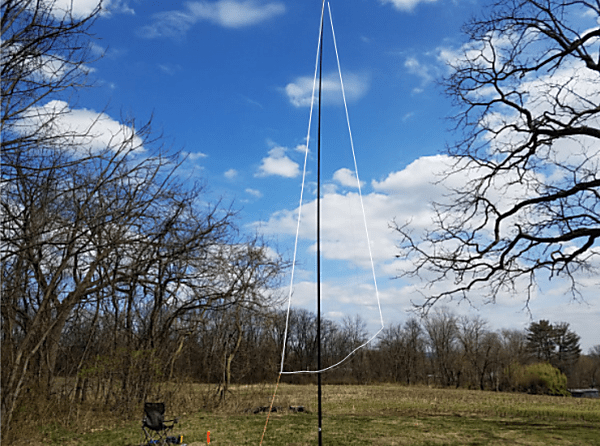
For my initial tests, I used a 28-foot Jackite pole to support the antenna. I only partially-extended the pole, such that the bottom of the antenna was about 4 to 5 feet off the ground. I used some nylon twine and a couple of tent stakes to tie off the two bottom corners.
This is the delta loop set up for my intial testing. The light-colored wires were difficult to photograph, so I enhanced them for visibility.
The setup was somewhat more complicated than most portable antennas I use. It took me about 20 minutes to get it set up, but I suppose that wasn’t too bad for my first time.
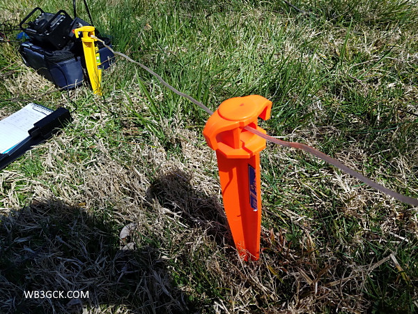
I used a couple of large tent stakes to keep the feedline off the ground. I connected the antenna to my KX3 using a 4:1 balun and a 1-foot piece of coax.
I used a couple of large tent stakes to keep the balanced feedline portion of the antenna off the ground.
Results
I first did a quick check to see what bands the KX3’s internal antenna tuner would handle. I found that I could load it up on every band from 60M through 6M, although I couldn’t get the SWR below 2:1 in the low end of 40M. That’s not surprising for a 20M loop, I suppose. I did have a usuable match between 7.030 and 7.060, where I normally operate.
I was only about 50 yards away from some powerlines, but the loop seemed quiet on receive.
On 20M, a French station answered my third CQ. I also made contacts with Missouri and wrapped up with yet another French station.
From the signal report the last station gave me, this antenna appears to do reasonably well with DX on 20M running QRP. It was a chilly and windy day, so I didn’t stay out there to try for contacts on other bands.
Wrap-Up
Although my initial outing with this antenna was promising, I need to spend some more time using it on bands other than 20M. In any event, it was a fun—and cheap—antenna project.
73, Craig WB3GCK
References:
[1] DeMaw, D. (1991). Technical Bits & Pieces. In W1FB’s QRP Notebook (2nd Edition, pp. 157–161). Newington, CT: QST. [2] DeMaw, D., & Aurick, L. (1984, October). The Full-Wave Delta Loop at Low Height. QST, 24–26.
In a recent post, I covered some (very) basic information about the venerable doublet antenna. This time around, I’ll cover some practical examples. These are antennas I have used and one unique design I know of.
Doublet Fed with TV Twinlead
My go-to portable antenna for several years was a simple doublet fed with 25 feet of that cheap, brown TV twin-lead. For the radiating elements, I used some #22 stranded hookup wire.
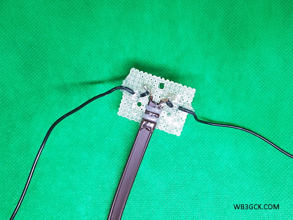
I first built the antenna as a 40M dipole fed with RG-174 coax. After a while, I wanted to cover multiple bands, so I removed the coax and replaced it with the twin-lead. I used a small piece of fiberglass perf board for the center insulator.
I have often used my homebrew Z-match tuner to load it up, although a 4:1 balun and a short run of coax to my rig’s internal tuner works fine, too. The whole antenna weighs next to nothing, and fits in a sandwich-sized Ziplock® bag.
Nothing fancy but it works great.
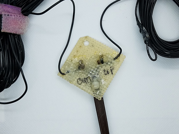
This is the center connector for my 66-foot doublet. The feedline is the old, cheap TV twin-lead.
Up and Outer
The Up and Outer is simply a doublet with one vertical leg and one horizontal leg. I had done some experimenting with this old-time antenna and decided to build one to use while on vacation in the Outer Banks of North Carolina.
I planned to support the vertical leg with a 28-foot Jackite pole, so I made a simple modification to a 44-foot doublet I had on the shelf. I spliced 6 feet of additional wire to each of the elements down to 28 feet each, and I was in business. Like my 40M doublet, the Up and Outer is fed with TV twin-lead and uses a perf board center insulator.
This antenna always goes with me on our annual Outer Banks vacation. I’ve used it from numerous beach rental houses, and it’s perfect for use on a second story deck. I used it last summer with great results, connecting it directly to my KX3. And, if I need to, I can use it as a normal horizontal doublet.
Appalachian Trail (AT) Dipole
This design is the brainchild of my friend, Ed Breneiser WA3WSJ, and goes back about 20 years. Rich Arland K7SZ, wrote about it in his QRP column in QST [1] back in 2001 and devoted a few pages to it in one of his books [2].
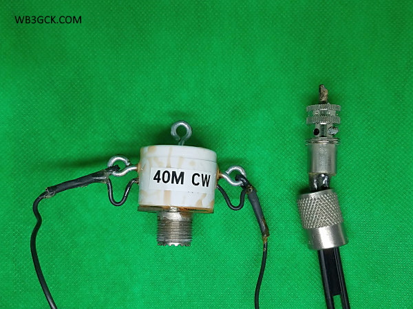
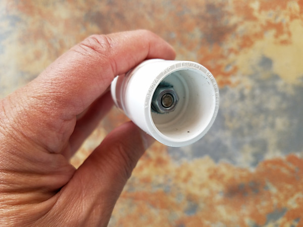
In simplest terms, it’s a 40M doublet made from #26 copper-clad stealth wire. Ed used a 3/4-inch PVC end cap for the center insulator (see photo). After soldering wires to an SO-239 socket and routing the wires through the end cap, the inside of the end cap is potted with epoxy. This makes it pretty much bomb-proof.
The antenna is fed with 300-ohm ladder line, which is soldered to a PL-259 UHF connector. The PL-259 probably causes a slight imbalance, but in the field, you’ll never notice it. You can also feed it with coax and use it as a normal 40M dipole. Pretty cool, huh?
When I built mine, I went with some #22 stranded hookup wire I had on hand. Although I departed from Ed’s design a bit, this doublet has been a reliable portable antenna over the years.
My version of the WA3WSJ AT Dipole. The discoloration on the PVC end cap is from a mishap I had while potting it with epoxy. On the right is a PL-259 connector used with 300-ohm ladder line. As you can probably tell, this antenna has seen years of heavy use.
WV0H Park Doublet
Myron WV0H designed a unique doublet that he dubbed The WVØH Park Portable Doublet. He uses two 50-foot pieces of wire to create a 60-foot doublet fed with a built-in open-wire feeder. I won’t attempt to offer a detailed description here; Myron’s blog post provides all the details you need to build one. Go check it out.
While I’ve never used Myron’s unique antenna, I can vouch that it works. I worked Myron a few years back while he was out in a park with his doublet. I can attest that it puts out a great QRP signal.
Wrap-Up
Well, that’s about it. If you need a reliable, easy-to-build, multi-band antenna, give the time-tested doublet a try.
73, Craig WB3GCK
References: [1] Arland, R. (2001, July). QRP Power – Antenna Time. QST, p. 100. [2] Arland, Richard K7SZ, Low Power Communication – The Art and Science of QRP, The American Radio Relay League, 2nd Edition, 2004, Chapter 6, pp. 6-36, 6-37
I was recently going through my stash of portable wire antennas and came across one of my old favorites—the doublet. I don’t see too many references to this type of antenna these days, but the doublet provides a great portable antenna option.
What is it?
The doublet, simply put, is just a dipole. The difference is that you feed it with a balanced feeder, rather than coax.
Hams have been using doublets for many years. The earliest reference I could find in the ARRL QST archives was from September of 1929.[1] In this write-up, Clair Foster W6HM describes a 40M doublet fed with twisted wire lamp cord used for receiving.
Advantages of the Doublet
The balanced feeder provides some advantages. Depending on how it’s constructed, it can withstand higher SWR with lower losses than coax. Because of the low losses at high SWR, you can use the doublet as a multi-band antenna.
As a portable antenna, it’s hard to beat, especially as an inverted vee. Use a tree branch or telescopic pole to hoist up the center, tie off the ends, and you’re in business. [2]
Some Disadvantages
This multi-band capability comes with some disadvantages, though. Fortunately, none of them are insurmountable.
First, you’ll need a transmatch that can handle balanced feedlines. Typical commercially-available feedlines have either 300 or 450-ohm characteristic impedances. For open-wire feedlines, the impedance can sometimes be 600 ohms or more.
I’ve had success using a homebrew Z-match tuner. Companies like Pacific Antenna and QRP Guys sell Z-match tuner kits that will handle balanced lines. They offer tuners that are small and light enough for QRP-portable use.
You can also use a balun to transition from the balanced feedline to 50-ohm coax. While this isn’t an optimum approach, it works. Textbooks often recommend a 4:1 balun, and that’s a good starting point. If you go this route, I recommend keeping the coax as short as practical. If you run into matching problems on some bands, try another balun ratio (e.g., 1:1), or change the length of your feedline.
The second drawback is that you need to be careful of how you route balanced lines. You need to avoid getting it too close to metal or laying it on the ground. Both can upset the line’s balance. This can cause it to radiate or introduce losses. If you have excess line, don’t coil it up. Operating outdoors, I found these restrictions aren’t very difficult to work around; you just need to be mindful of them.
Construction
Building the doublet is pretty simple. Many folks suggest making the doublet a half-wavelength long at the lowest band you intend to use. I’ve built one for 40M and it worked well on 40M and higher. Depending on your tuner, it may also be usable on the next lower band.
L. B. Cebik W4RNL (SK) popularized the 44-foot doublet for 40M-10M. According to Cebik’s analysis, this length produces a more consistent radiation pattern across the bands.
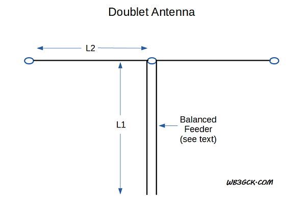
Doublet diagram. One rule-of-thumb suggests avoiding combinations of feedline electrical length (L1) and one leg of the radiator (L2) that are odd multiples of an eighth-wavelength.
Regardless of the size of the doublet, you should try to avoid certain feedline lengths. One rule-of-thumb suggests avoiding combinations of feedline electrical length plus one leg of the radiator that are odd multiples of an eighth-wavelength. [3] If you run into matching problems, you can try adjusting the length of either the feedline or the radiating elements.
Feedline Options
You have several options here:
Commercial 450-ohm or 300-ohm ladder line. These are commonly available, and they work great.
Homebrew open-wire feeders. This is the most efficient option. If you do some Internet searching, you’re likely to find lots of ways to build open-wire feeders. SOTABEAMS has a great example on their website.
TV twin-lead. I’ve used the cheap, brown stuff quite a bit for portable doublets. Unfortunately, it’s nearly impossible to find these days. If you come across it somewhere, stock up!
Lamp cord or speaker wire. This works and I’ve seen folks use it for portable antennas. However, it can be lossy, compared to window line or open-wire feeders.
More Later
If you want more technical details on this antenna, information abounds on the Internet and in antenna books. In particular, Cebik wrote some great articles that are worth searching for.
In a future post, I’ll cover some practical examples that I have come across or used in the field.
73, Craig WB3GCK
References: [1] Foster, C. W6HM (1929, September). Experimenters’ Corner: The “Doublet” for Receiving. QST, p. 39. [2] DeMaw, D. W1FB (1991). Technical Bits & Pieces. In W1FB’s QRP Notebook (2nd Ed., pp. 157–161). Newington, CT: QST. [3] Heys, John D., G3BDQ (1989). Center-fed antennas using tuned feedlines. In Practical Wire Antennas. Bedford, UK: Radio Society of Great Britain, p 7.
[NOTE: This is an updated version of an old article from my QSL.NET website. In the interest of full disclosure: My local dollar store no longer sells the speaker wire I used. While it’ll probably cost you a few more bucks to build one, it’ll still be a cheap antenna. Although the original article has been on my website for 15 years, I still get the occasional email from folks who have built one.]
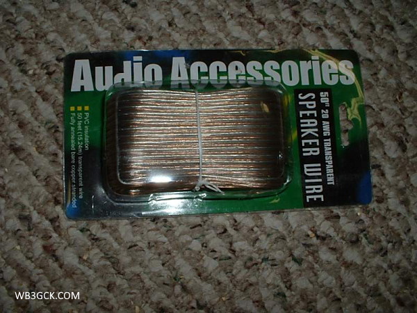
I love rummaging through our local dollar store. One of the biggest bargains in our local dollar store is speaker wire. You can get 50 feet of two-conductor speaker wire for a buck. Not too shabby. I always keep a bunch of the stuff on hand for antenna experimentation.
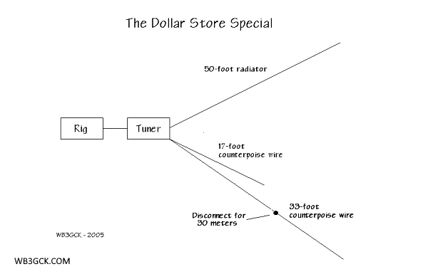
Diagram of the Dollar Store Special. See the text for other counterpoise/radial options.
Using a single 50-foot roll of dollar store speaker wire, I made a simple 50-foot random wire antenna with counterpoise wires to cover the 40, 30 and 20-meter bands. I stashed the whole kit in a zip-lock sandwich bag and always keep it on hand as a backup antenna system whenever I operate in the field. With a simple antenna tuner of some sort, this will get you on the air in a pinch, should your primary antenna fail.
This is the 20 AWG speaker wire I used. Sadly, my local dollar store no longer carries it. I wish I had stocked up while it was available.
Here’s all you have to do:
Separate the conductors so that you now have two separate 50-foot wires.
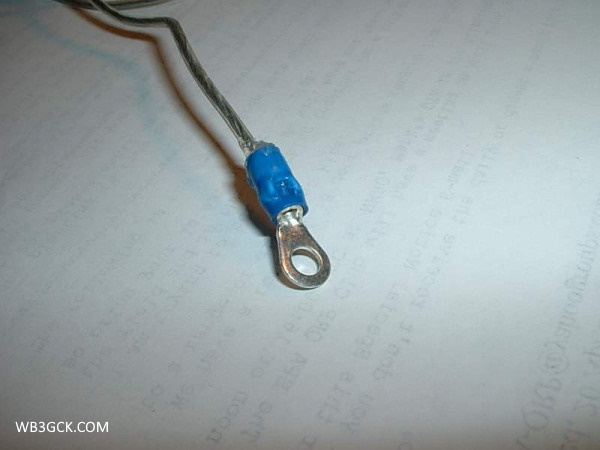
For the radiator, take one of the 50-foot wires and crimp a small ring lug to one end—right over the insulation. This gives you someplace to tie a line to hoist it up. On the other end, just strip off a half-inch or so of the insulation. You can leave it bare or add whatever kind of connector you want; whatever works best with your tuner.
For the counterpoise wires, take the remaining 50-foot wire and cut it so that you have a 33-foot wire and a 17-foot wire. If you only want to work 40 and 20 meters, you can stop right here. You now have counterpoise wires for both of these bands.
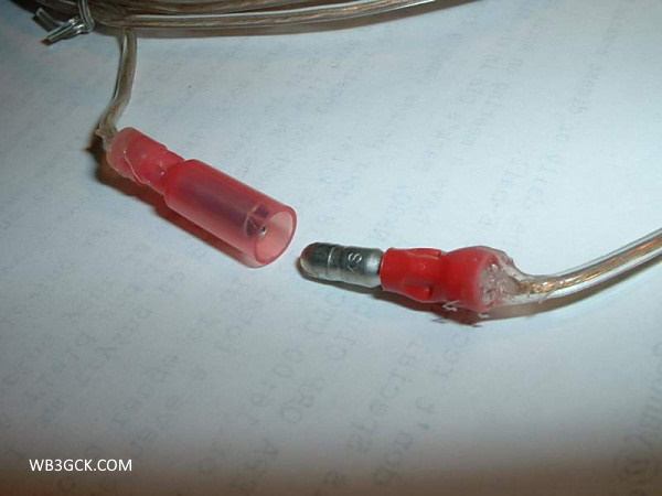
To provide a counterpoise wire for 30 meters, take the 33-foot wire from Step #3 and cut it so that you now have a 23-foot wire and a 10-foot wire. Strip off about 1/2-inch of insulation from one end of the 23-foot wire. Install a quick-disconnect connector of some sort on the other end, so that you can join the 23-foot and 10-foot wire sections together. The idea here is that, with the two wires connected, you have a 33-foot counterpoise wire for 40 meters. With the two sections separated, you now have a 23-foot counterpoise wire for 30 meters.
I used a ring terminal to terminate the 50-foot wire. Note that the terminal is crimped over the wire’s insulation. The metal ring terminal is electrically-isolated from the antenna wire.
This is the quick-disconnect connector I used on the original version of the counterpoise wire. I used some Goop® adhesive to provide some strain relief.
[Note: If you only plan to operate with the radials laying on the ground, cutting them to resonance isn’t too important. You can simplify things a bit by going with just the 33 and 16-foot wires. I think two 25-foot wires would be sufficient, as well. Three 16.6-ft radials is another option to consider. Feel free to experiment here and see what works for you.]
In operation, just hoist one end of the 50-foot radiator up in a tree or other suitable support. Connect the other end to the hot side of your tuner. Connect the 33-foot and 17-foot counterpoise wires to the ground connection on your tuner and lay them out on the ground. When you want to work 30 meters, just disconnect the quick-disconnect on the longer counterpoise wire. Pretty simple, eh? Any type of simple L-tuner should work fine for this.
Please note that I wouldn’t recommend using this wire for a permanent outdoor antenna. It’s not suited for that kind of use. But for temporary outdoor use, it’ll do just fine. Besides, if the wire goes bad, you can always replace the whole thing for a dollar!
You have probably seen Amazing GOOP® in your local hardware store. This product with the funny-sounding name has been around for decades. I’ve been using it for ham radio applications for the past 25 years or so.
I recently did some extensive research on Amazing GOOP. (Full disclosure: OK. I lied. My “extensive research” merely consisted of a quick Google search and reading a Wikipedia article.) Back in 1972, a senior executive in the aerospace industry created a product called “Shoe GOO®.” Shoe GOO was intended to repair rubber-soled shoes. In fact, I first used it many years ago to repair a pair of rubber fishing waders. The original Shoe GOO is still produced by Eclectic Products. They also produce a wide variety of waterproof, flexible adhesives for a host of applications and environments. The Amazing GOOP® product line is what I’ve been using for ham radio applications.
Here are some of the uses I’ve found for it:
Sealing portable antenna connections. This was my original use for Amazing GOOP. After soldering the connections between the feedline and dipole elements, I seal them up with Amazing GOOP. I’ve never had any corrosion problems like you can run into with RTV.
This is the center connector of the doublet that I use for my “Up and Outer” antenna. I used Amazing GOOP to seal the soldered connections and help anchor the wires in place. This particular antenna was built about 15 years ago and is still holding up well.
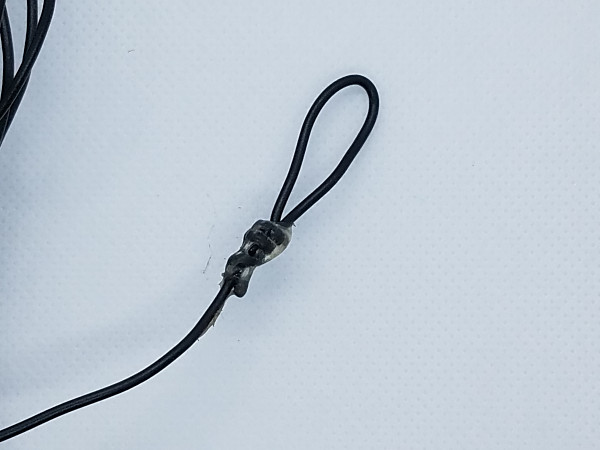
Wire end loops. Instead of end insulators for my portable wire antennas, I just form small loops. I twist the wire to form a loop and use Amazing GOOP to hold the wire twists in place. (This works very well for my lightweight portable wire antennas but I would use end insulators for permanent antennas.)
End loop on one of my (many) wire antennas for portable use. I attach my throwing line directly to the loop, foregoing an insulator. With smaller diameter wire, I sometimes put some shrink wrap over the GOOP.
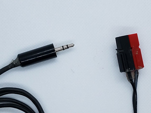
Powerpole® connectors. I’m a “belt and suspenders” kind of guy. So, I crimp and solder my Powerpole connectors. After I assemble and test them, I apply some Amazing GOOP where the wires enter the connector housing. This provides strain relief and makes them very rugged. I also place a dab of GOOP on both ends of the roll pin. This keeps them from popping out in the field.
Miniature audio connectors. I’m hard on the little 1/8″ audio plugs I use on my CW keys. So, after soldering and testing them, I put some GOOP on the connections before screwing on the plastic housing. Then, I put some GOOP on the wires where they enter the connector to add strain relief. I also apply GOOP to spade/ring lugs after they are crimped and soldered.
A 3.5mm plug and Anderson Powerpole connector after I have applied GOOP as a strain relief. Sure, they look a bit ugly but these connectors are pretty much bomb-proof. These items have seen heavy use in the field over the past 3 or 4 years.
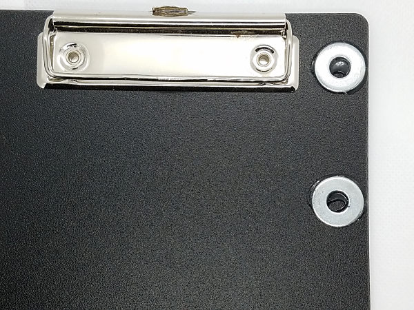
My CW Clipboard. I used GOOP to attach the steel washers to the clipboards I use in the field. The washers are how I attach the magnetic bases of my portable paddles and straight key to the clipboard.
I used GOOP to attach the steel washers to the clipboards I use in the field. The washers are used to attach the magnetic bases of my portable paddles and straight key.
My rainspout antenna. I use a liberal amount of GOOP to seal the connection to my trusty rainspout antenna. GOOP holds up well to the continuous exposure to the elements.
Hopefully, the pictures will clarify my descriptions.
If I can find it, I use one of the GOOP varieties intended for outdoor use for my rainspout and portable wire antennas. Right now, I’m using Amazing GOOP Max. Regular old household variety of Amazing GOOP is fine for most uses, though. For all applications, I like to let the GOOP cure overnight before use.
A few disclaimers are in order:
This stuff is permanent. Be sure whatever you’re using it on works before sealing it up with GOOP.
This stuff works for me, as described. I don’t know what you’re using it for or how you’re using it, so your results may vary.
I have absolutely no financial interests in this product. I’m just a satisfied consumer.
Here’s yet another quick little hack. I raided my junk box to cobble together a ground mount for my portable vertical. While this solved a couple of specific issues I had, it might only be of interest to a few of you folks out there.
I often support my 19-foot vertical with one of those inexpensive fishing poles from eBay. (I paid around $10 USD for my 7.2M pole.) I had been using a simple method for ground mounting. I shove a screwdriver in the ground, take the bottom cap off of the pole, and place the pole over the screwdriver. Voila!
While the screwdriver technique is a useful way to support my vertical, there are two issues with it. First, the screwdriver method places the bottom of the pole in direct contact with the dirt. This can gunk up the threads on the bottom of the pole. (Ask me how I know.) Next, since my homebrew 19-foot vertical takes up the entire length of the pole, the matchbox ends up too close to the ground for my liking. I made a simple little gizmo that addresses both of these issues.
Antenna ground mount in use with my 19-foot vertical
From some scraps and junk I had on hand, I used the following:
Duct tape (optional, for a better fit between the 1/2-inch PVC and the bottom of the pole)
A dab of Lock-Tite thread locker
[Note: The PVC pipe I used works with the particular pole I use. If the bottom of your pole has a different inside diameter, you might need to use a different size pipe.]
I joined the two pieces of PVC pipe together with the PVC reducer. Then I glued the two end caps together, back-to-back. Next, I drilled a 1/4-inch hole through the center of the two end caps. I fastened the stainless steel rod with two nuts and a lock washer. I also used a dab of thread locker for good measure. I had to do some sanding on the 3/4-inch pipe to allow the end caps to slide on and off easier. At this point, you might want to put a layer or two of duct tape on the 1/2-inch pipe for a snug fit inside the pole.
The two main assemblies of the antenna ground mountStainless steel rod bolted through the two back-to-back PVC end caps
In the field, I place the end cap assembly on the 3/4-inch pipe and shove the rod into the ground. The pole goes over the 1/2-inch PVC pipe, of course. This places the bottom of the pole about 8 inches above the ground. With lightweight poles, guying is unnecessary. For travel, I flip the end cap assembly around so that the bolt stores inside the pipe. This prevents poking holes in my backpack or bicycle pannier bags.
Antenna ground mount assembled for useAntenna ground mount configured for travel. The stainless steel rod is stored safely inside the PVC pipe assembly.
The threads on the end of the stainless steel rod pick up some dirt in use. It’s not a major problem but I might cut the rod off just above the threads. I haven’t decided yet.
That’s all there is to it. I’m hoping the accompanying pictures clarify how I built it.
I was long overdue for some outside QRP-portable operating. Although we had some heavy rain overnight, it looked like it would be gone by mid-day. So, yesterday I headed out to nearby Towpath Park to take advantage of some milder temperatures.
I had a couple of objectives for today. First, I was hoping to make some QRP to the Field (QTTF) contest QSOs. I also wanted to test a new ground mount I put together for my cheap eBay telescopic pole.
When I got to the park, the rain had stopped. Unfortunately, last night’s heavy rains left the park a bit on the swampy side. That, coupled with some gusting winds, would make for an interesting test of my new ground mount. I was a bit leary but went ahead and set up the antenna anyway.
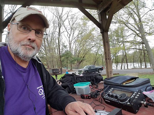
As I was setting up, a Pennsylvania Fish & Boat Commission officer got out of his car and walked up the path towards me. While it’s true that I was using a fishing rod (for my antenna), I was about 50 yards away from the river! As he approached, I told him that I was a ham radio operator. He said, “I know.” As it turns out, he was also a ham and had spotted my callsign on my license plate. He was just stopping by to say hello. As we talked a bit, we also found out that we also had some former employers and co-workers in common. Small world!
WB3GCK at Towpath Park
As we were chatting, the gusting wind blew my antenna over to a 45-degree angle. The ground was too soggy to hold my antenna mount. It never fell over, so I gave my antenna mount a passing grade for this extreme test. Unfortunately, in my rush to straighten out the antenna, I never took a picture. Pity. It put that tower in Pisa to shame. I moved the antenna a few feet to a somewhat drier spot and that did the trick. I’ll show a closer look at my ground mount in a future post.
My vertical ground-mounted in the soggy ground. This picture was taken while Mother Nature was on a brief break from trying to blow my antenna over.
When I finally got on the air, I found the bands dominated by Michigan and Ontario QSO Party stations. I didn’t hear any QTTF stations at all. So, I spent some time handing out points to some of the QSO Party stations.
After a while, I had had enough of the wind and packed up my gear. As I was packing up, the sun came out and the wind subsided. Go figure!