As I mentioned in an earlier post, I bought the little American Morse MS2 straight key intending to somehow magnetically attach it to the clipboard I use for portable operating. It took some thinking but I came up with a workable solution. I might come up with a better solution in the future but, for now, it should suffice.
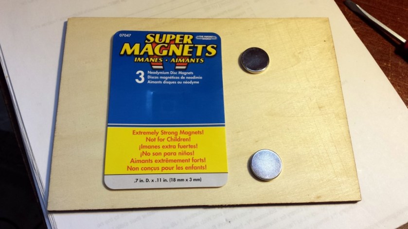
What I set out to do was build a wooden mount that could attach the MS2 that held two magnets that lined up with the steel washers on the clipboard. I had a couple of “super magnets” that I planned to use. The problem I ran into is that the magnets are almost too strong to attach directly to the washers. My solution was to enclose the magnets within the wood base.
Super magnets. Boy, these things are powerful!
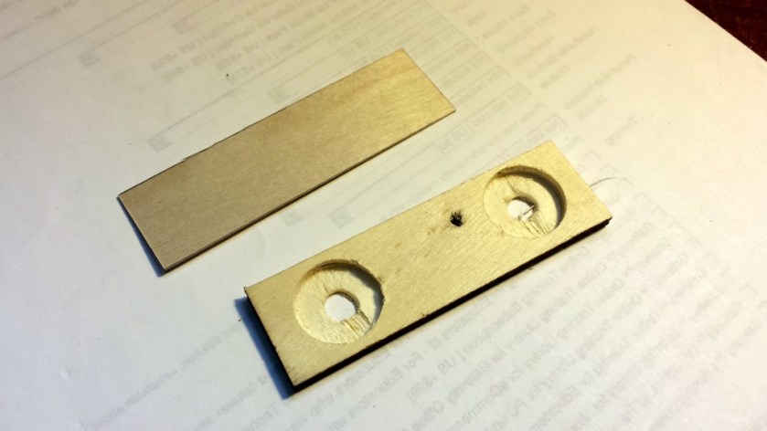
I cut a 1×3.25-inch piece of 1/8-inch plywood. Then I drilled two 3/4-inch holes just deep enough to fit the magnets. After placing the magnets in the holes, I glued on a thin wood veneer. This puts some extra spacing between the magnets and the washers on the clipboard. After drilling a mounting hole for the MS2, I sprayed on a couple of coats of paint.
Wood pieces prior to assembly
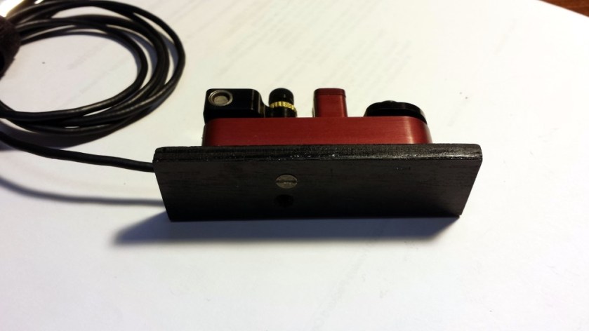
After letting the paint dry, I went to attach the key to the base. Oops! I drilled the mounting hole from the wrong side of the mount. My first inclination was to putty it in and repaint. However, I decided to leave it there as a constant reminder to always measure twice and drill once!
MS2 attached to the magnetic base. Don’t look too closely or you might see the drilling mistake I made.
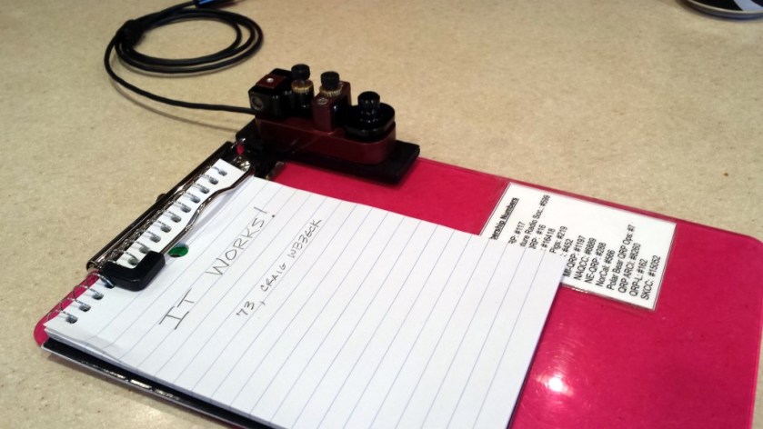
The mount actually works well. The concealed super magnets hold the key firmly to the clipboard without the need for excessive force to remove it. Once I free up some time, I’ll give it a thorough test out in the field.
Here’s a little battery pack I put together for use as an external, portable power source for my YouKits HB-1B. I wanted something relatively lightweight and inexpensive that would put out at least 13 volts. This solution has fit the bill, so far.
There isn’t too much to it. I already had some Li-Ion cells on hand, so I wanted to make use of them. They are 18650 cells with a 6000 maH rating. I haven’t actually verified the claimed capacity but most cells tend to be somewhat over-rated. These particular cells are the “protected” type; each cell contains some circuitry that prevents overcharge and over-discharge. There are much cheaper unprotected cells but I’d rather be safe than sorry.
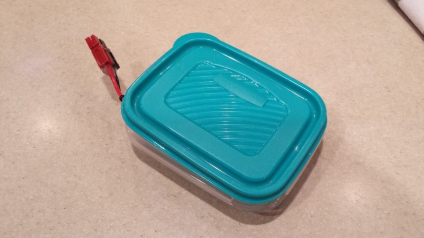
Battery pack with cable stowed
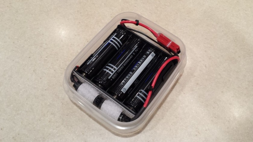
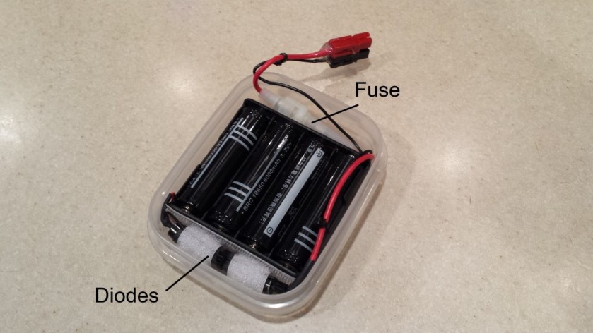
To put it together, I bought a 4-cell battery holder for 18650-size cells. With 4 fully charged cells, the voltage can exceed 16 volts. To keep the voltage below 14 volts (the maximum for my HB-1B), I put 3 silicon diodes in series with the output. This brings the voltage down to about 13.7 volts with fully charged cells. I also added a 2-amp fuse and an Anderson Powerpole connector.
Li-Ion battery pack layout
To package it, I had a sandwich-sized Rubbermaid container that wasn’t being used. It turned out to be the perfect size to hold everything snugly. When not in use, everything is neatly tucked inside the container. In use, I lift one corner of the lid to bring out the connector.
Battery pack as I normally use it
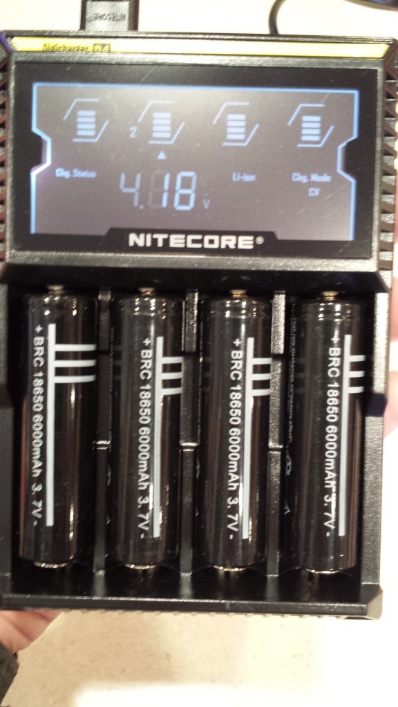
For charging, I remove the cells from the holder and charge them with a Nitecore D4 charger. This is a 4-bay smart charger. It automatically detects the type of battery inserted and applies the proper charging method. Each bay works independently, so balanced charging is not an issue. The D4 works with a variety of battery types (Ni-Cad, NiMH, Li-Ion, etc.) so it is a handy accessory in the shack.
Nitecore D4 smart charger. Each cell is charged independently.
I haven’t done any formal testing of this battery arrangement, but it has provided adequate power for an afternoon of portable operating. For extended operating sessions, I throw 4 extra cells in my backpack that I can swap in if needed.
It’s not the most elegant solution but it works fine.
One of my favorite portable antennas is a 30-ft wire fed through a 9:1 unun. This type of antenna generally the uses coax feeder as a counterpoise, since the 9:1 unun configuration provides no line isolation. Most of the time, this has worked well for me with no issues with stray RF getting back into the equipment.
On a couple of occasions, my Elecraft T1 auto tuner began to act up, refusing to load up on one or more bands. (Running through the T1’s diagnostic mode always seems to restore operation to normal.) I’ve also had one of my keyers behave erratically once or twice. Since this has only happened when using the 9:1 unun, my suspicion is that common-mode RF currents on the coax shield are the culprit.
My proposed solution for this is to use a line isolator between the tuner and the coax feeder. (Note: Using a line isolator at the antenna end of the coax would defeat the purpose in using the coax as a counterpoise.) A quick survey of my junk box stash of parts showed I had everything I need to build a line isolator from scratch.
Parts List
RG-174/U coax (approximately 24 inches)
FT-140-43 ferrite core
(2) BNC-F chassis mount connectors
Hammond Manufacturing 1591MSBK Enclosure (2.2 x 3.3 x 0.8 inches)
Construction
This is a very simple project. You can build one in well under an hour.
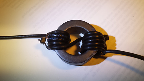
The RG-174 coax is wound on the FT-140-43 core for a total of 10 turns. Take note of how the 5th turn goes across the core. This makes installation in the case a little easier. I used a couple of small nylon tie-wraps to hold the windings in place.
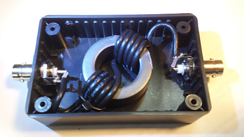
Drill the holes for each of the BNC connectors and wired up the choke, as shown. I used a 5/64-inch drill bit and had to use a reamer to get the holes to the right size for the BNC connectors I used.
Solder the coax to the BNC connectors.
To mechanically secure the core, I used a piece of two-sided foam mounting tape to mount the choke to the bottom of the case. As an additional precaution, I put a piece of packing foam on top of the choke before attaching the lid. This foam provides a slight downward pressure on the choke to prevent it from shaking loose in the case during handling.
Core windingCore installed in case
Testing
I don’t have access to the equipment necessary to do any type of exhaustive testing of the line isolator. In lieu of that, I hooked it up to a 50-ohm dummy load and checked the SWR. It was basically flat from 160M through 6M. While that tells me nothing about how effective it is in reducing common-mode currents, I at least know I didn’t make any serious screw-ups in building it.
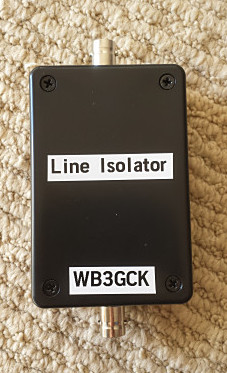
Completed line isolator
In Operation
Well, this part will have to wait until I have a chance to get out for some portable operating. I want to make sure that the line isolator doesn’t affect the T1’s ability to tune my antenna. Since the initial problems were very intermittent, only time will tell if I solved those problems or not. I’ll be sure to update this post with any new insights I gain.
Update 5/16/2017:
Since this article seems to get a lot of traffic, I figured it was time for a long-overdue update. Not long after this post was published, I tested this 1:1 unun in line with the coax to my 30-foot wire and 9:1 unun. As I suspected it might, it affected the tuning of the antenna. One or two bands wouldn’t load up properly. This made sense to me, since this antenna configuration relies on the shield of the coax for the counterpoise. So, there’s some RF on the coax shield by design. This device obviously is blocking some RF, as it should. I haven’t pursued it further and I still have done any measurements to determine its effectiveness. With a change of connectors on the output side, it could definitely be useful as a 1:1 balun, I suppose.