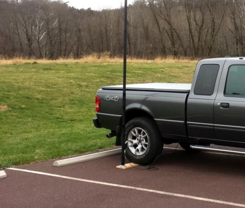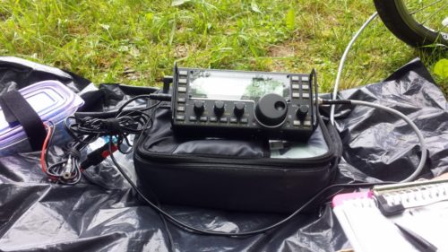
I bought a lightweight telescoping pole on eBay a while back. It collapses down to 26 inches and weighs less than 12 ounces. Best of all, I only paid around $10 for it. While it was advertised as a 7.2-meter pole (approximately 23.6-feet), it actually measures about 19.5-feet when extended. This pole was just begging for some sort of antenna to support.
After trying different types of non-resonant wires with it, I decided to build some sort of resonant antenna. For quick excursions to the field, I often take the AlexLoop. However, sometimes it’s nice to have something a bit more frequency-agile. I wanted something that is easy to deploy and could cover the 40, 30, and 20-meter bands.
I started off planning to build a vertical with a 16.5-ft radiator to make it resonant on 20 meters. I could then build some loading coils to make it resonant on 40 and 30 meters. In the end, I went a slightly different way with this antenna.
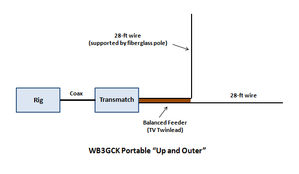
With the lousy band conditions lately, I spend most of my time on 40 meters. I decided to take advantage of the full length of the pole. So, my concept was to use a 19-foot radiator with loading coils for 40 and 30. On 20M and higher, I would use the radiator as a random wire and use a tuner.
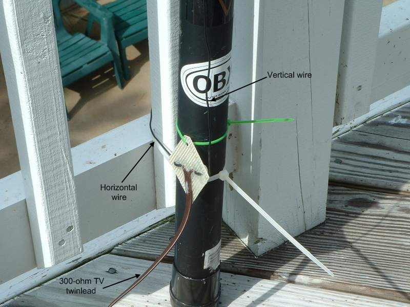
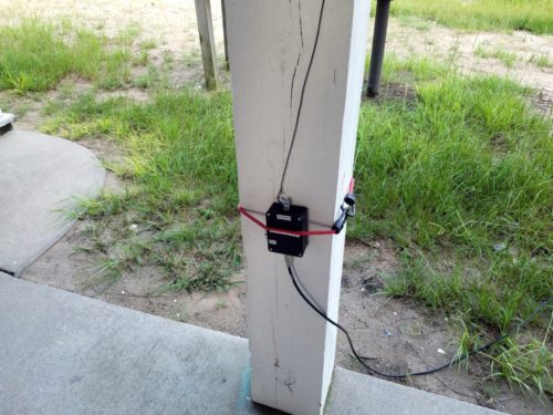
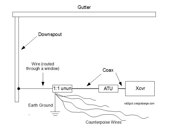
As you can see in the schematic, I feed the antenna through a 1:1 choke, consisting of 10 bifilar turns of #22 hookup wire on an FT140-61 toroid. I calculated the values for the loading coil using some online calculators (see notes below). From there, I went through several iterations of testing and adjusting to arrive at the final values. For the 40M loading coil, I ended up with 29 turns of #22 enameled wire on a T130-2 toroid. I made a tap at 11 turns for the 30M band.
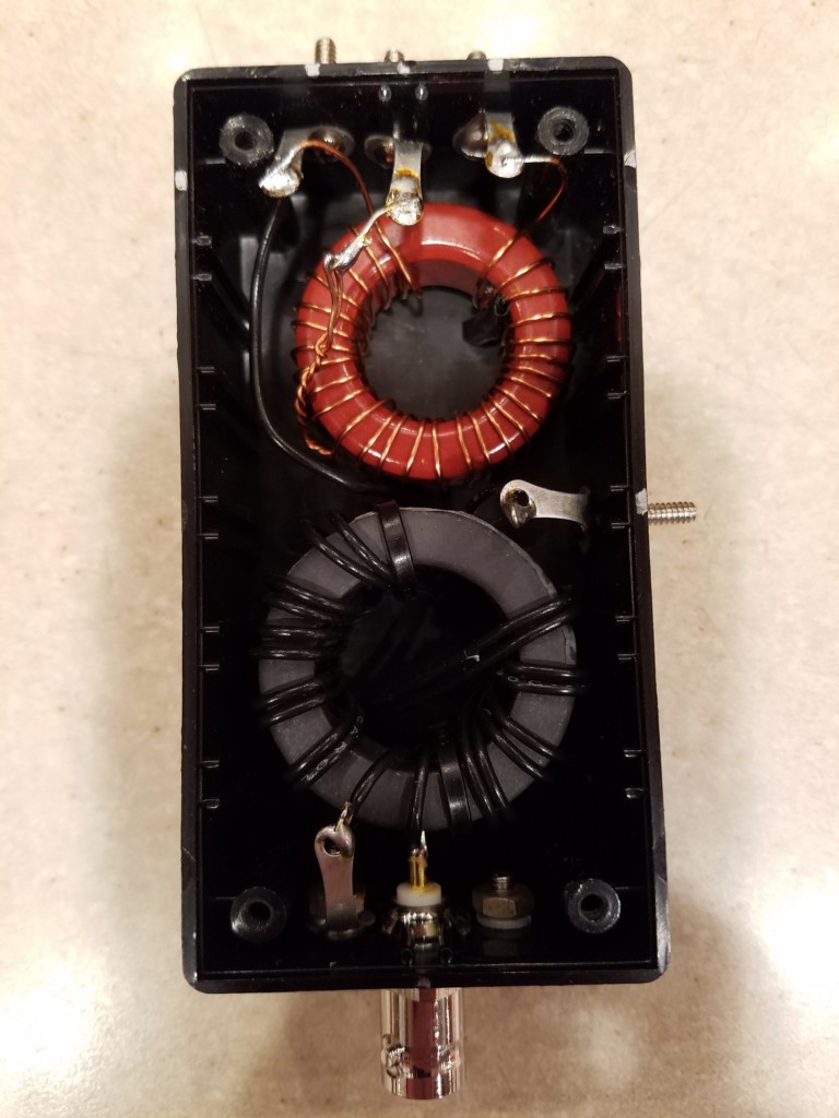
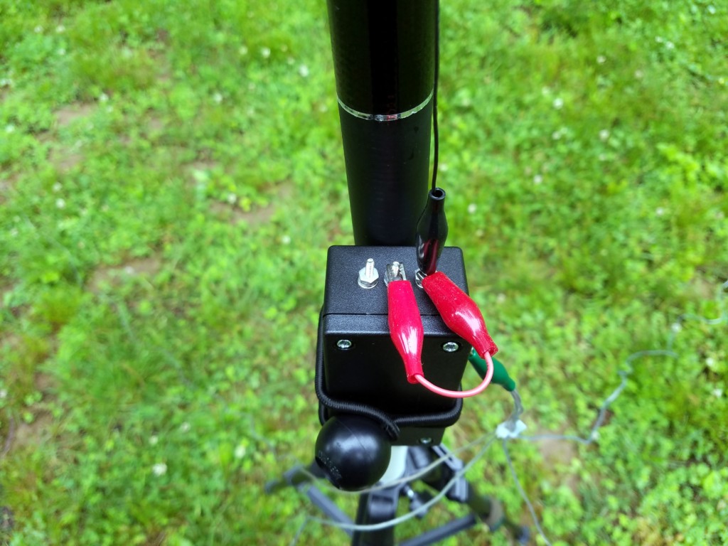
I mounted both coils in a small box and used some small bolts to make the tap points accessible for band changing. I also made a little jumper with alligator clips to short out various portions of the loading coil for the different bands.
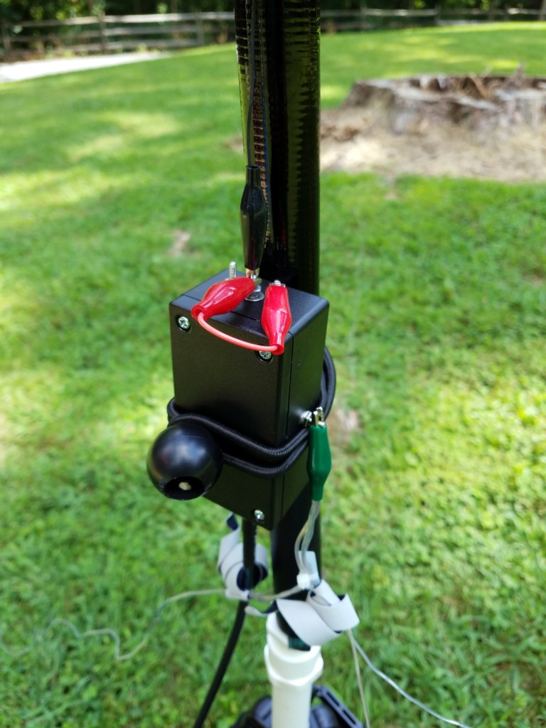
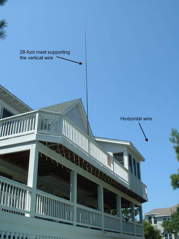
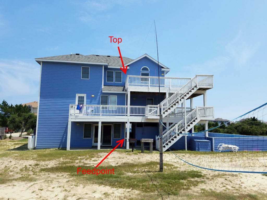
The pole won’t support much weight, so I built the 19-foot radiator from #26 Stealth wire (Part #534) from the Wireman. Because the pole is made from carbon fiber, I try to let the top of the pole bend over slightly, to keep the wire away from the pole. I don’t know how much influence the carbon fiber pole would have on tuning but I figure I’d avoid introducing another variable.
For radials, I used a 25-foot roll of cheap speaker wire and used it to throw together four 12.5-foot radials. Again, I grabbed what I had on hand and went with it. While the four radials seem to be working out OK, I plan to add a couple more for good measure.
I should note that all the materials here were selected based on availability in my junk box. So, there’s certainly plenty of wiggle room here for experimenting.
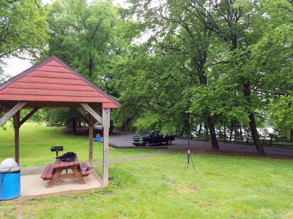
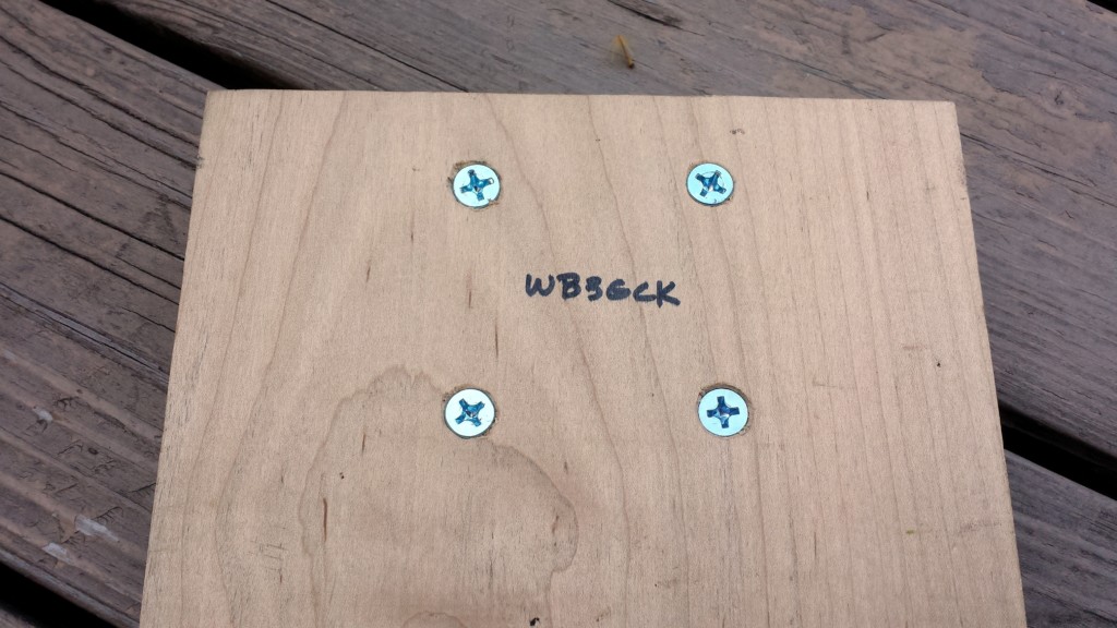
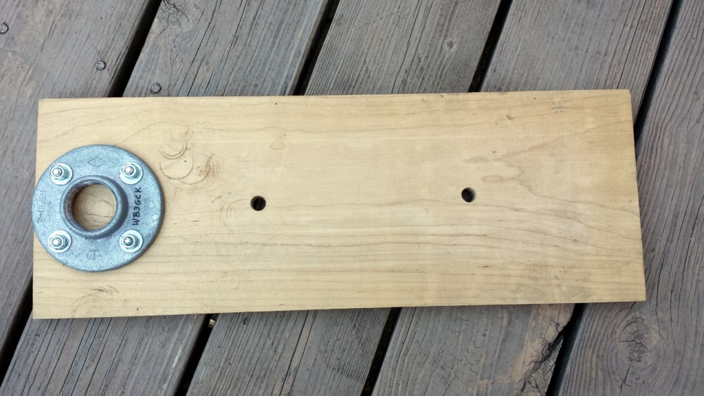
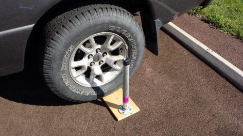
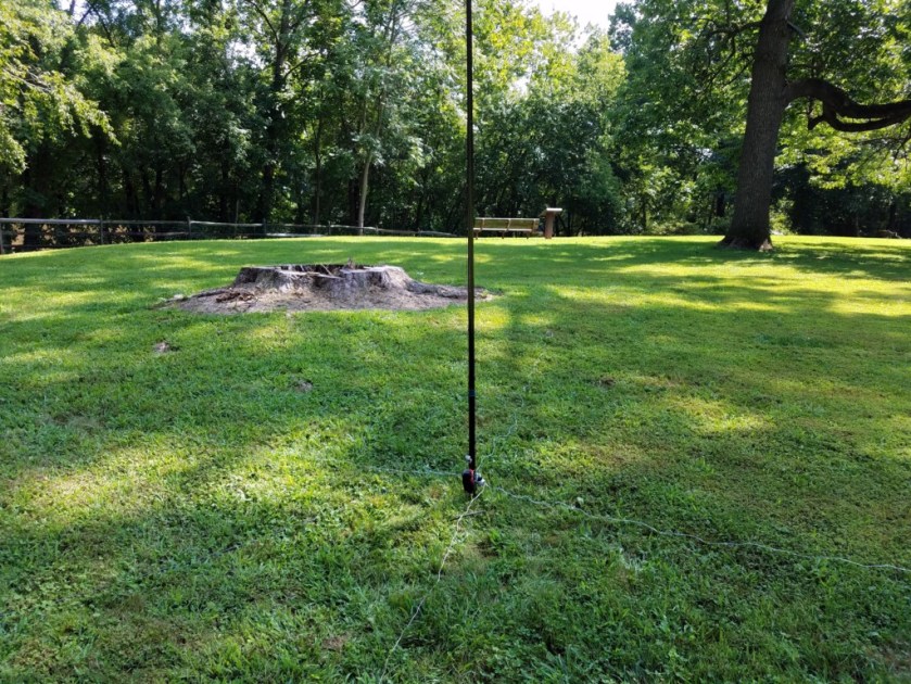
I made up a little tripod adapter out of some PVC pipe. One end slides over the post on my tripod, while the other end slides up inside the bottom of the collapsible pole. I also found a screw driver with a handle that fits nicely inside the bottom of the pole. So, for ground-mounting, I can just shove the screwdriver in the ground and place the pole on top of it. This works surprisingly well and allows me to leave the tripod at home.
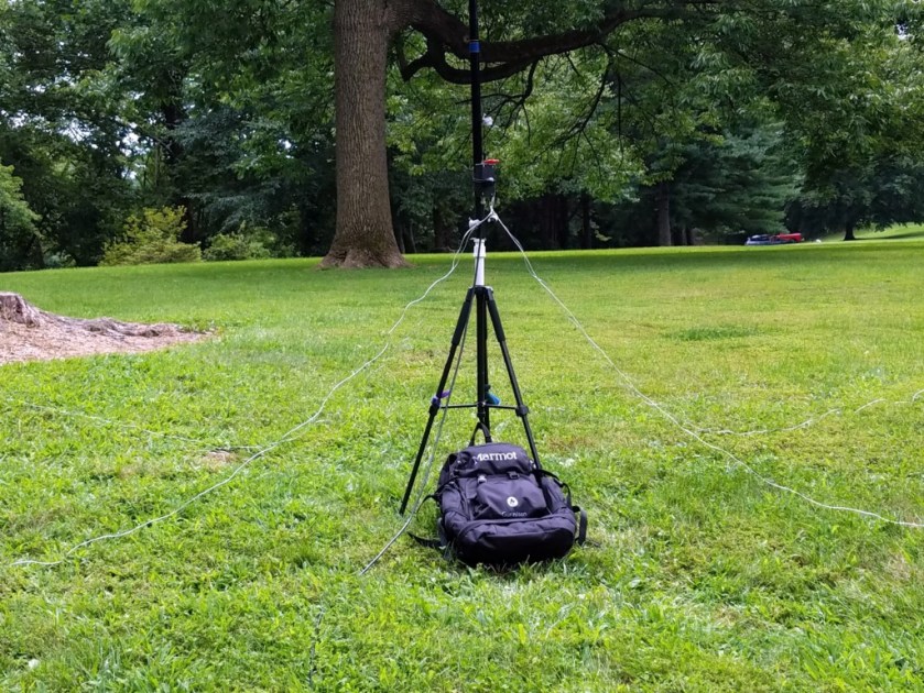
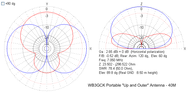
After considerable tweaking I ended up with SWRs of less than 2:1 across the entire 40M band and less than 1.5:1 across the 30M band. On 20M and higher, the tuner in my KX3 loads it up with no problems.
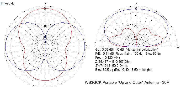
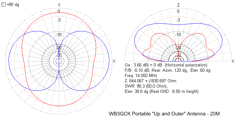
I’ve been very pleased with the results on 40M so far. It seems to radiate pretty well. I’ve also made contacts on 30M and 20M but, honestly, I need to use it more on those bands to get a better feel for the performance. It’s hard to evaluate antennas when the band conditions are as poor as they have been lately.
Although the antenna works, there are a few things I would do differently, if I were to build another one:
- My physical packaging could be better. While the enclosure I used is nice and compact, it’s a little cramped for experimentation. During development, coil adjustments were tough.
- Separate coils for 40M and 30M would make the tuning much easier. The tapped coil was a challenge to adjust.
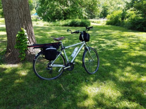
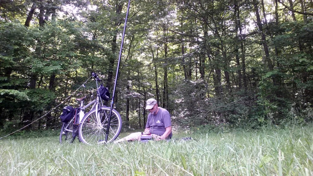
I like the form factor and easy setup of this antenna. I can set it up in a few minutes and it is very easy to transport by backpack or bike. Now to give it some more air time in the field.
Time will tell if it’s a keeper.
72, Craig WB3GCK
Notes:
- Loading coil calculator: http://www.k7mem.com/Ant_Short_Dipole.html (Note: The calculator I originally used for this project is no longer online. This calculator should work. Just use one leg of the dipole.)
- Toroid calculator: http://www.66pacific.com/calculators/toroid-coil-winding-calculator.aspx