Once again, the NJQRP Skeeter Hunt contest coincided with our annual family vacation to the Outer Banks of North Carolina. I’m certainly not a hardcore contester, but I wanted to set aside some time to make a few contacts from North Carolina. Although our rental house was beautiful, it presented some challenges for ham radio.

After a long drive down and all the unloading/unpacking the day before, I didn’t feel like getting too crazy putting up an antenna. Although this was our first time in this rental house, I had a good feel for the layout from online research.
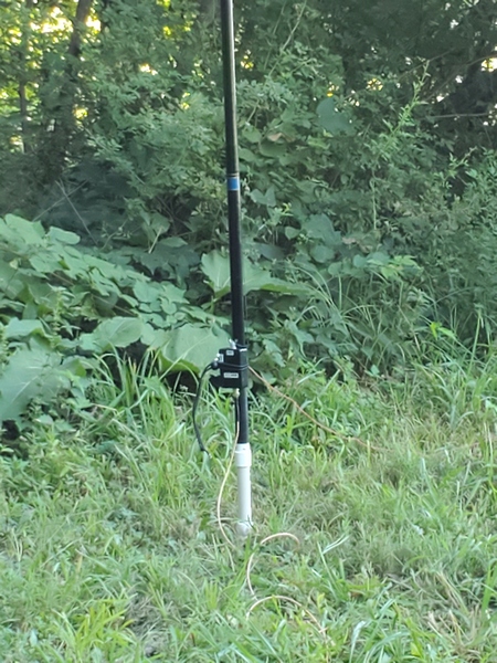
My previous experience has shown that these rental properties come with a lot of RF noise, both from within the house and from neighboring houses. The house this year was no exception. So, I stayed away from vertical antennas near the house and went with an end-fed random wire sloper.
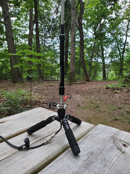
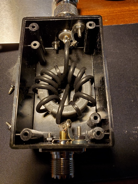
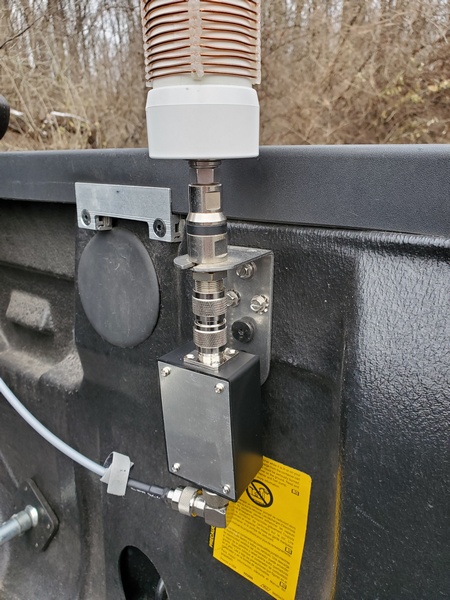
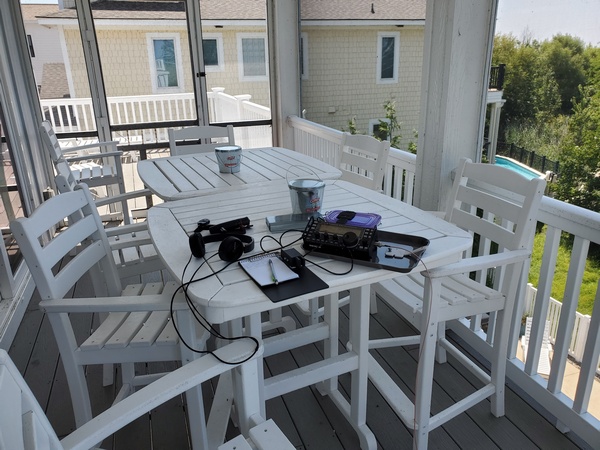
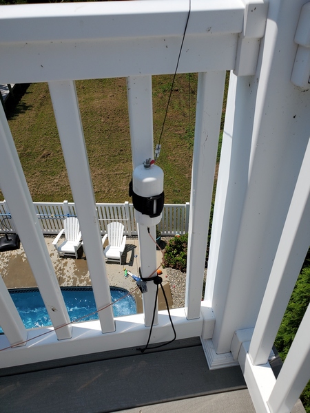
The antenna this year was a 35-foot wire, sloping down from the 3rd-story deck. I fed it through my homebrew weather-resistant 9:1 unun and ran 25 feet of coax into a screened-in porch on the same level. I attached the end of the wire to a fence around the pool area, making sure it wouldn’t get in anyone’s way. The wire was a bit long, so I ran the last two feet horizontally along the top of the fence.
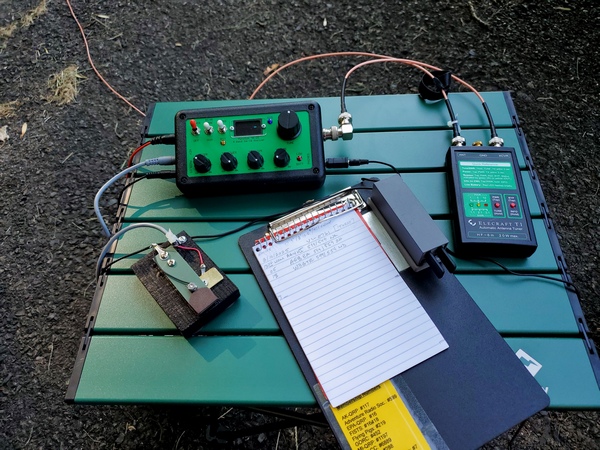
I fired up my KX3 and checked the bands. A quick contact with a POTA activator on 40M confirmed it was putting out some sort of signal. The noise on 40M, however, was horrendous in places. The higher bands were better but still somewhat noisy. I hunted four POTA activators while experimenting with the antenna. Two of the contacts were easy, while the other two were tough going.
I also had to contend with some audio interference from my grandkids having fun in the pool down below. Anticipating this, I brought along a pair of over-the-ear headphones this year. Unfortunately, the headphones were no match for four exuberant kids.
Once the contest started, the noise level on 40M was about S3 in parts of the band, and S5-S7 in other parts. There was also a loud noise signal that would slowly sweep across the band from time to time. Despite the noise, I worked four skeeters and one very confused QRO station who wasn’t in the contest. He probably thought I was a POTA activator and couldn’t figure out why I needed to know his power output.
Up on 20M, the noise was lower but still present. I didn’t hear much Skeeter Hunt activity, despite getting some respectable hits on the Reverse Beacon Network. I ended up with a pair of Missouri skeeters in the log. I tried calling CQ on 15M with no luck.
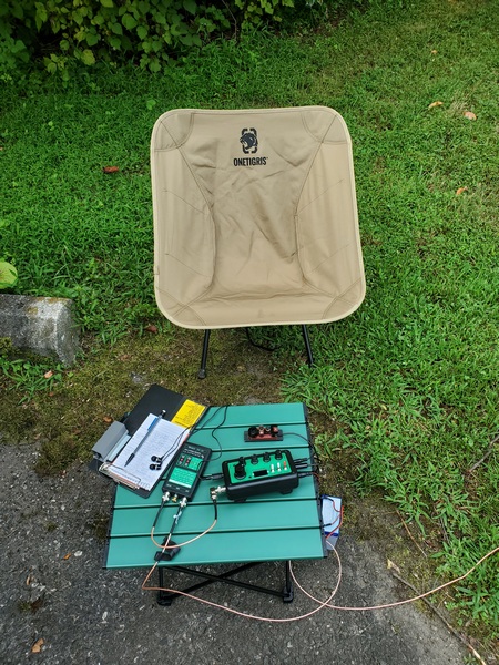
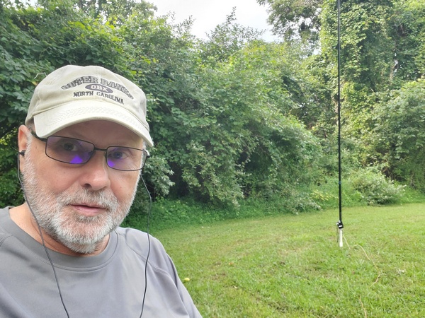
After a little over an hour, I threw in the towel. My operating position was facing west across Currituck Sound, so my nice shady spot was giving way to the afternoon sun. Before I pulled the plug, I had one last contact on 40M with a friend back in Pennsylvania.
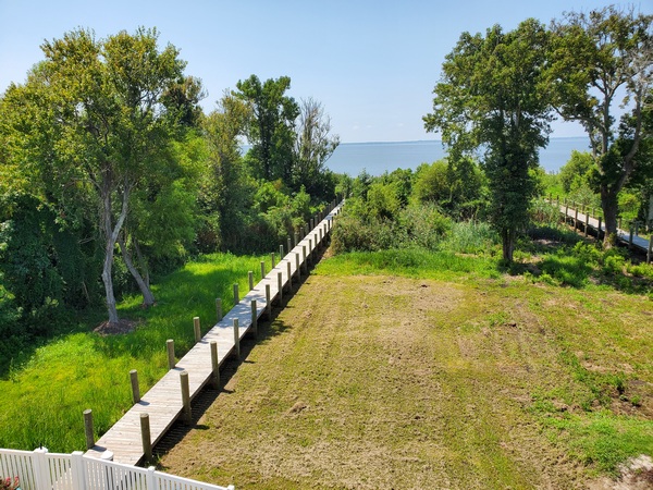
So, my 2025 Skeeter Hunt results were less than stellar. Although it was frustrating working through the noise, I still had fun. Plus, the scenery from my temporary “shack” was outstanding.
72, Craig WB3GCK