Speaker Wire Delta Loop

Here’s an example of what can happen when you have a hunk of cheap wire and a little too much time on your hands.

Years back, I did a write-up on a simple, random wire antenna made from a 50-foot roll of speaker wire from a local dollar store. I nick-named it the Dollar Store Special. I had a similar roll of wire in my junk box, so I set out to see if I could build another useful portable antenna from it.

This time out, I wanted to build something more elaborate than a random wire. After some sketching with a pencil and paper, I came up with this simple portable delta loop.

There are certainly better ways to construct a delta loop. However, I just wanted to see if I could build a functional antenna using only cheap speaker wire. So, with that in mind, here’s how I did it.

The Design

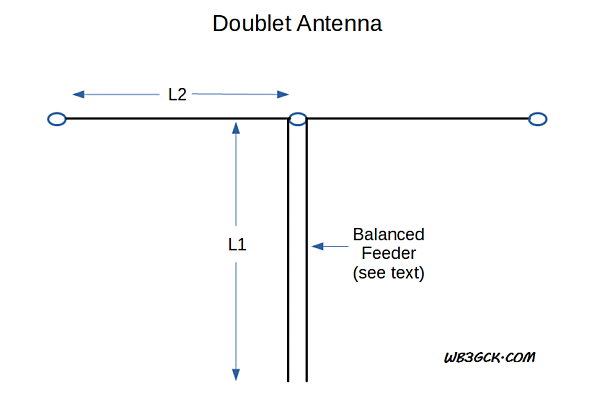
The antenna I built was inspired by a portable delta loop designed by Doug DeMaw, W1FB. [1] Doug’s multiband delta loop was designed for the 40M band and used a 300-ohm balanced feeder. 

According to Doug’s book, this type of antenna should work well on the fundamental frequency and higher. For the next band below the fundamental, he suggests connecting the feeder wires together and using it like a random wire. I figured I’d just try loading it up as is to see what happens.

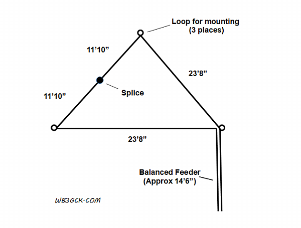
Given that I constrained myself to a 50-foot roll of speak wire, I scaled my antenna for the 20M band. Using the formula, 1005 divided by the frequency in megahertz, I calculated a total length of 71 feet (21.6 meters) for the center of the 20M band. That would leave some of the two-conductor wire for an improvised balanced feeder.

Feeding the delta loop in a corner (with the apex of the loop pointing up), gives the antenna vertical polarity with a low take-off angle.[2] As with most antennas, higher is better. However, this antenna is still quite useful at practical heights in the field.

Since a tuner will always be necessary, I expended no effort trying to optimize the design.

Construction

Schematic diagram of the delta loop antenna

If you’re a visual person like me, refer to the diagram to help make sense of the directions below.

  1. Measure off 35.5 feet from one end of the speaker wire. Place a small zip-tie around the wire at this point.
  2. Separate the 35.5-foot end of the speaker wire into two separate wires.
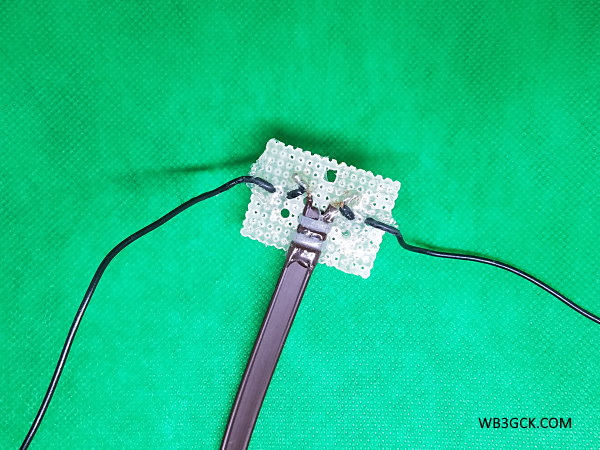
  3. Strip and solder the loose ends of the 35.5-foot wires together. Put some electrical tape or shrink tubing over the splice.
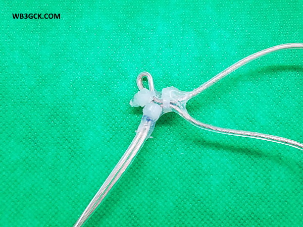
  4. Make 3 small loops in the wire, as shown in the diagram. You can see an example in the accompanying photo. These are going to be the attachment points. I used some Goop® adhesive on the zip-ties to help hold things in place.
  5. Finally, install some spade terminals on the ends of the shorter conductors. These will be used to attach the antenna to your tuner or balun.
Example attachment point. This is the feedpoint of the antenna. The two wires to the right are part of the loop antenna, while the wires towards the bottom serve as the balanced feedline. I used some Goop® adhesive on the zip-ties to help hold them in place.

Deployment

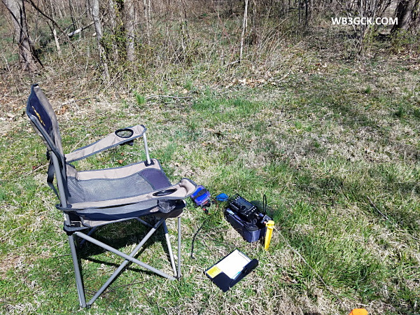
For my initial tests, I used a 28-foot Jackite pole to support the antenna. I only partially-extended the pole, such that the bottom of the antenna was about 4 to 5 feet off the ground. I used some nylon twine and a couple of tent stakes to tie off the two bottom corners.

This is the delta loop set up for my intial testing. The light-colored wires were difficult to photograph, so I enhanced them for visibility.

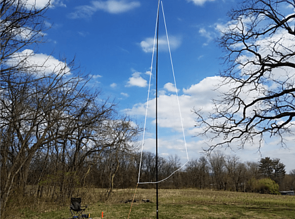
The setup was somewhat more complicated than most portable antennas I use. It took me about 20 minutes to get it set up, but I suppose that wasn’t too bad for my first time. 

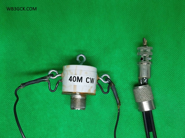
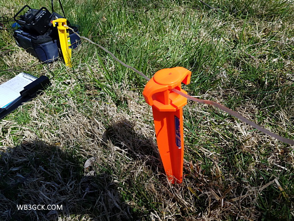
I used a couple of large tent stakes to keep the feedline off the ground. I connected the antenna to my KX3 using a 4:1 balun and a 1-foot piece of coax. 

I used a couple of large tent stakes to keep the balanced feedline portion of the antenna off the ground.

Results

I first did a quick check to see what bands the KX3’s internal antenna tuner would handle. I found that I could load it up on every band from 60M through 6M, although I couldn’t get the SWR below 2:1 in the low end of 40M. That’s not surprising for a 20M loop, I suppose. I did have a usuable match between 7.030 and 7.060, where I normally operate.

I was only about 50 yards away from some powerlines, but the loop seemed quiet on receive. 

On 20M, a French station answered my third CQ. I also made contacts with Missouri and wrapped up with yet another French station. 

From the signal report the last station gave me, this antenna appears to do reasonably well with DX on 20M running QRP. It was a chilly and windy day, so I didn’t stay out there to try for contacts on other bands. 

Wrap-Up

Although my initial outing with this antenna was promising, I need to spend some more time using it on bands other than 20M. In any event, it was a fun—and cheap—antenna project.

73, Craig WB3GCK

References:

[1] DeMaw, D. (1991). Technical Bits & Pieces. In W1FB’s QRP Notebook (2nd Edition, pp. 157–161). Newington, CT: QST.
[2] DeMaw, D., & Aurick, L. (1984, October). The Full-Wave Delta Loop at Low Height. QST, 24–26.

Socially-Distant Antenna Testing

With the COVID-19 pandemic, I have been spending a lot of time at home lately. We had some decent weather today, so I went out to do some portable operating while practicing social distancing.

My daughter and son-in-law recently purchased an old farmhouse that they are restoring. The farmhouse is located on a large piece of property with plenty of room for QRP-portable operating. No one was there today, so I had all that acreage to myself. That made the social distancing thing easy. 

I had a portable delta loop antenna that I built a year or two ago but never tested. Today seemed like a good time to try it out. I set the antenna up behind an old barn and operated my KX3 from a camp chair. (I’ll be doing a detailed write-up on this antenna soon.)

My operating position today

I spent some time seeing which bands the KX3 would tune. Once that initial testing was done, I tuned up on 20M and started calling CQ. After the third CQ, I received a call from fellow SKCC member F8FSC in France. We both struggled with fading, but I was thrilled that he heard my meager 5-watt signal.

I bumped my power up to 10 watts to improve my odds. I heard N3PDT calling CQ from Missouri and gave him a call. We exchanged SKCC numbers and chatted for a bit. 

Tuning down the band, I heard F6HKA booming in from France. I sent my callsign once, and he got it the first time. Bert gave me a 549 and said I was peaking at 569. We exchanged SKCC numbers and chatted for about 10 minutes before signing. I’ve worked Bert many times, and it’s always a pleasure.  

It was sunny but somewhat chilly and windy out there today. As I was working Bert, though, it started getting cloudy. I was starting to feel the cold, so I figured it was a good time to pack up and head home.

It felt great to be playing radio outside and not thinking about the pandemic.

Stay safe, everyone.

73, Craig WB3GCK

Doublets I Have Known and Loved

In a recent post, I covered some (very) basic information about the venerable doublet antenna. This time around, I’ll cover some practical examples. These are antennas I have used and one unique design I know of.

Doublet Fed with TV Twinlead

My go-to portable antenna for several years was a simple doublet fed with 25 feet of that cheap, brown TV twin-lead. For the radiating elements, I used some #22 stranded hookup wire.

I first built the antenna as a 40M dipole fed with RG-174 coax. After a while, I wanted to cover multiple bands, so I removed the coax and replaced it with the twin-lead. I used a small piece of fiberglass perf board for the center insulator.

I have often used my homebrew Z-match tuner to load it up, although a 4:1 balun and a short run of coax to my rig’s internal tuner works fine, too. The whole antenna weighs next to nothing, and fits in a sandwich-sized Ziplock® bag.

Nothing fancy but it works great.

This is the center connector for my 66-foot doublet. The feedline is the old, cheap TV twin-lead.

Up and Outer

The Up and Outer is simply a doublet with one vertical leg and one horizontal leg. I had done some experimenting with this old-time antenna and decided to build one to use while on vacation in the Outer Banks of North Carolina. 

I planned to support the vertical leg with a 28-foot Jackite pole, so I made a simple modification to a 44-foot doublet I had on the shelf. I spliced 6 feet of additional wire to each of the elements down to 28 feet each, and I was in business. Like my 40M doublet, the Up and Outer is fed with TV twin-lead and uses a perf board center insulator.

This antenna always goes with me on our annual Outer Banks vacation. I’ve used it from numerous beach rental houses, and it’s perfect for use on a second story deck. I used it last summer with great results, connecting it directly to my KX3. And, if I need to, I can use it as a normal horizontal doublet.

Appalachian Trail (AT) Dipole

This design is the brainchild of my friend, Ed Breneiser WA3WSJ, and goes back about 20 years. Rich Arland K7SZ, wrote about it in his QRP column in QST [1] back in 2001 and devoted a few pages to it in one of his books [2].

In simplest terms, it’s a 40M doublet made from #26 copper-clad stealth wire. Ed used a 3/4-inch PVC end cap for the center insulator (see photo). After soldering wires to an SO-239 socket and routing the wires through the end cap, the inside of the end cap is potted with epoxy. This makes it pretty much bomb-proof. 

The antenna is fed with 300-ohm ladder line, which is soldered to a PL-259 UHF connector. The PL-259 probably causes a slight imbalance, but in the field, you’ll never notice it. You can also feed it with coax and use it as a normal 40M dipole. Pretty cool, huh? 

When I built mine, I went with some #22 stranded hookup wire I had on hand. Although I departed from Ed’s design a bit, this doublet has been a reliable portable antenna over the years. 

My version of the WA3WSJ AT Dipole. The discoloration on the PVC end cap is from a mishap I had while potting it with epoxy. On the right is a PL-259 connector used with 300-ohm ladder line. As you can probably tell, this antenna has seen years of heavy use.

WV0H Park Doublet

Myron WV0H designed a unique doublet that he dubbed The WVØH Park Portable DoubletHe uses two 50-foot pieces of wire to create a 60-foot doublet fed with a built-in open-wire feeder. I won’t attempt to offer a detailed description here; Myron’s blog post provides all the details you need to build one. Go check it out.

While I’ve never used Myron’s unique antenna, I can vouch that it works. I worked Myron a few years back while he was out in a park with his doublet. I can attest that it puts out a great QRP signal.

Wrap-Up

Well, that’s about it. If you need a reliable, easy-to-build, multi-band antenna, give the time-tested doublet a try.

73, Craig WB3GCK

References:
[1] Arland, R. (2001, July). QRP Power – Antenna Time. QST, p. 100.
[2] Arland, Richard K7SZ, Low Power Communication – The Art and Science of QRP, The American Radio Relay League, 2nd Edition, 2004, Chapter 6, pp. 6-36, 6-37

The Doublet – Revisiting a Classic Antenna

I was recently going through my stash of portable wire antennas and came across one of my old favorites—the doublet. I don’t see too many references to this type of antenna these days, but the doublet provides a great portable antenna option.

What is it?

The doublet, simply put, is just a dipole. The difference is that you feed it with a balanced feeder, rather than coax. 

Hams have been using doublets for many years. The earliest reference I could find in the ARRL QST archives was from September of 1929.[1] In this write-up, Clair Foster W6HM describes a 40M doublet fed with twisted wire lamp cord used for receiving. 

Advantages of the Doublet

The balanced feeder provides some advantages. Depending on how it’s constructed, it can withstand higher SWR with lower losses than coax. Because of the low losses at high SWR, you can use the doublet as a multi-band antenna. 

As a portable antenna, it’s hard to beat, especially as an inverted vee. Use a tree branch or telescopic pole to hoist up the center, tie off the ends, and you’re in business. [2]

Some Disadvantages

This multi-band capability comes with some disadvantages, though. Fortunately, none of them are insurmountable.

First, you’ll need a transmatch that can handle balanced feedlines. Typical commercially-available feedlines have either 300 or 450-ohm characteristic impedances. For open-wire feedlines, the impedance can sometimes be 600 ohms or more.  

I’ve had success using a homebrew Z-match tuner. Companies like Pacific Antenna and QRP Guys sell Z-match tuner kits that will handle balanced lines. They offer tuners that are small and light enough for QRP-portable use. 

You can also use a balun to transition from the balanced feedline to 50-ohm coax. While this isn’t an optimum approach, it works. Textbooks often recommend a 4:1 balun, and that’s a good starting point. If you go this route, I recommend keeping the coax as short as practical. If you run into matching problems on some bands, try another balun ratio (e.g., 1:1), or change the length of your feedline. 

The second drawback is that you need to be careful of how you route balanced lines. You need to avoid getting it too close to metal or laying it on the ground. Both can upset the line’s balance. This can cause it to radiate or introduce losses. If you have excess line, don’t coil it up. Operating outdoors, I found these restrictions aren’t very difficult to work around; you just need to be mindful of them. 

Construction

Building the doublet is pretty simple. Many folks suggest making the doublet a half-wavelength long at the lowest band you intend to use. I’ve built one for 40M and it worked well on 40M and higher. Depending on your tuner, it may also be usable on the next lower band.

L. B. Cebik W4RNL (SK) popularized the 44-foot doublet for 40M-10M. According to Cebik’s analysis, this length produces a more consistent radiation pattern across the bands. 

Doublet diagram. One rule-of-thumb suggests avoiding combinations of feedline electrical length (L1) and one leg of the radiator (L2) that are odd multiples of an eighth-wavelength.

Regardless of the size of the doublet, you should try to avoid certain feedline lengths. One rule-of-thumb suggests avoiding combinations of feedline electrical length plus one leg of the radiator that are odd multiples of an eighth-wavelength. [3] If you run into matching problems, you can try adjusting the length of either the feedline or the radiating elements.

Feedline Options

You have several options here:

  • Commercial 450-ohm or 300-ohm ladder line. These are commonly available, and they work great. 
  • Homebrew open-wire feeders. This is the most efficient option. If you do some Internet searching, you’re likely to find lots of ways to build open-wire feeders. SOTABEAMS has a great example on their website.
  • TV twin-lead. I’ve used the cheap, brown stuff quite a bit for portable doublets. Unfortunately, it’s nearly impossible to find these days. If you come across it somewhere, stock up!
  • Lamp cord or speaker wire. This works and I’ve seen folks use it for portable antennas. However, it can be lossy, compared to window line or open-wire feeders.

More Later

If you want more technical details on this antenna, information abounds on the Internet and in antenna books. In particular, Cebik wrote some great articles that are worth searching for. 

In a future post, I’ll cover some practical examples that I have come across or used in the field.

73, Craig WB3GCK

References:
[1] Foster, C. W6HM (1929, September). Experimenters’ Corner: The “Doublet” for Receiving. QST, p. 39.
[2] DeMaw, D. W1FB (1991). Technical Bits & Pieces. In W1FB’s QRP Notebook (2nd Ed., pp. 157–161). Newington, CT: QST.
[3] Heys, John D., G3BDQ (1989). Center-fed antennas using tuned feedlines. In Practical Wire Antennas. Bedford, UK: Radio Society of Great Britain, p 7.