My XYL has accused me of being obsessed with bags, backpacks, and storage containers of all sorts. She’s an excellent judge of character. This one, fortunately, wasn’t very expensive.
A few years ago I bought a backpack with ham radio in mind. I wanted one big enough to carry my Alexloop antenna, along with my QRP rig, battery, and, assorted emergency and survival-type gear. (I could survive a zombie apocalypse with all the stuff I put in that pack.) Although it continues to serve me well, at 35 liters it’s a bit overkill when I don’t need to carry all that stuff. I wanted something a bit smaller and lighter for short hikes and casual outings.
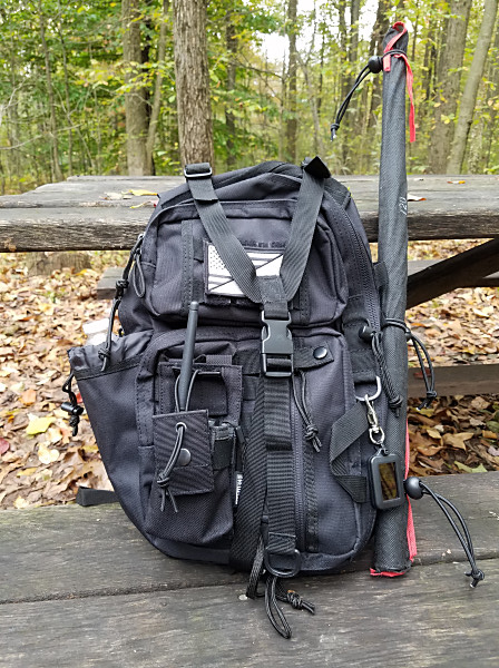
After looking at a dizzying array of small packs, I settled on the Rambler sling pack from Red Rock Outdoor Gear. It’s a bit larger than most other sling packs but I needed one that would accommodate my essential radio gear. It measures about 10 inches x 16 inches x 4 inches and has lots of compartments and MOLLE webbing.
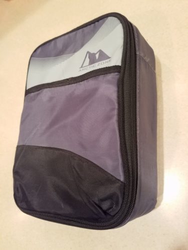
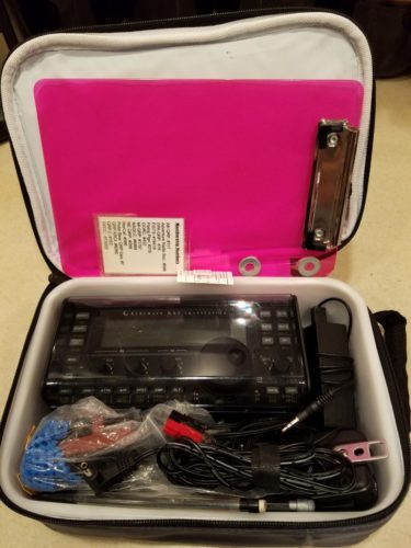
The main compartment comfortably accommodates the box that holds my KX3 and accessories. I also carry a LiFePO4 battery and my antenna wires in this compartment. I use one of the outer compartments to hold safety and comfort items, e.g., first aid kit, sunblock, insect repellent, emergency poncho, etc. In the remaining outer pocket, I keep a headlamp, emergency whistle, compass, a copy of my Amateur Radio license and a notepad and pencil. There’s a compartment on the back of the pack that’s perfect for carrying a folding sit pad and a large contractor garbage bag that I use as a ground cloth. With the water bottle pouch on the side of the pack, I don’t have to use up space inside the pack to carry water.
The Red Rock Sling Pack also does double-duty for public service events with my local ARES-RACES group. I just remove the QRP gear from the main compartment and replace it with my HTs, spare batteries, emergency vest, etc. Oh, did I mention snacks? Yeah, lots of snacks.
With all the MOLLE webbing on the pack, I couldn’t resist adding a few things. On the back of the pack, I added a pouch for my HT. I added a cell phone holder in the front on the shoulder strap. I use the webbing on one side of the pack to carry my telescopic fiberglass pole, which I fasten with some adjustable bungee cords. And just for the heck of it, I added some molle-compatible velcro strips for attaching a morale patch.
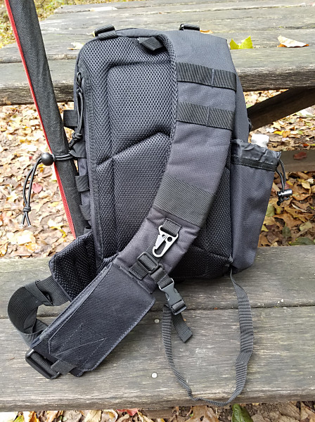
In use, I find it very comfortable. The padded strap is non-reversible and goes over my left shoulder. That’s my preference anyway. The zippers on this bag have all worked smoothly without a lick of trouble. (Nothing frustrates me more than balky zippers!)
After nine months of use, the sling pack is holding up well and has fit my needs exactly. It provides a handy and comfortable way of carrying my radio stuff out into the field. There certainly are more expensive packs available but, for less than $50.00 USD, the Red Rock Sling Pack has been money well spent.
Now, all I need is to find some time to get back out into the field for some QRP fun.
72, Craig WB3GCK
[Disclaimer: I have no financial interest in Amazon or any these products. I’m just a satisfied customer.]
Links:
Red Rock Outdoor Gear Rambler Sling Pack
Tactical MOLLE Smartphone Holster
OneTigris MOLLE Radio Holder
Del Molle Strips for Attaching Tactical ID Patches


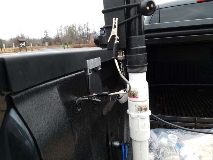


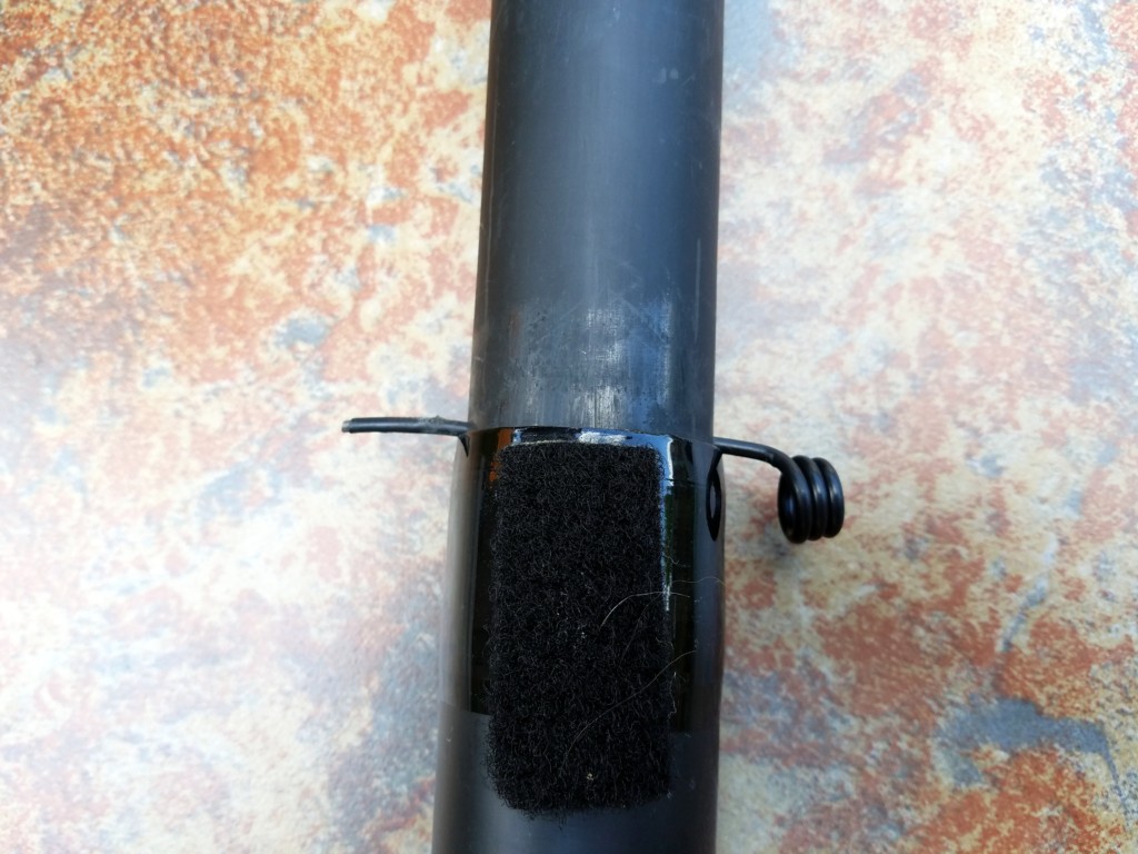
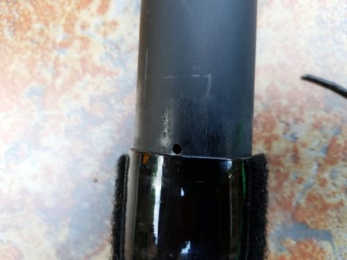 Here’s how it works. When the pole is fully extended, I just slide a pin through the two holes to prevent the pole from collapsing. For the pin, I used a hook from a bungee cord that I straightened out, using a pair of pliers. The resulting pin is just the right size and it has a nice rubberized coating on it. You could, of course, use something else (a nail, a piece of wire, etc.) for the pin.