We’re expecting some snow and sleet tomorrow, so I figured I head out for a little QRP-portable operating before the nasty weather moved in. So, I drove to nearby Black Rock Sanctuary for a quick outing.
The temperature today in southeastern Pennsylvania was a mild 42° F. I planned to operate from a picnic table using my AlexLoop clamped to the table. However, in my haste to get on the road, I neglected to put the AlexLoop in my truck. As Homer Simpson would say, “Doh!”
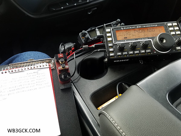
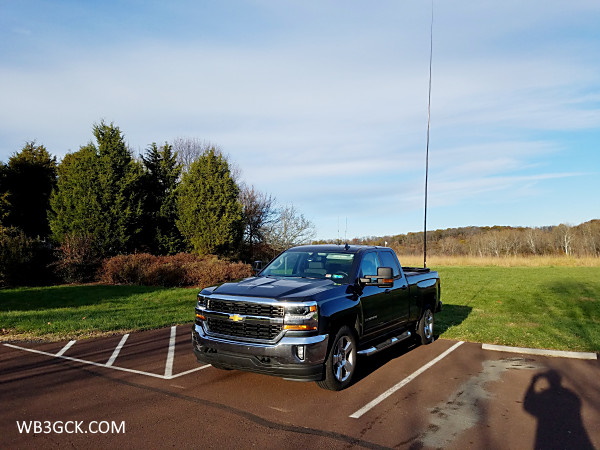
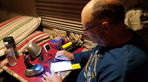
I had some antenna wires, but I didn’t think it was a good idea to mess with trees in a nature preserve. Fortunately, I always keep the necessary equipment for my stationary-mobile set-up in the truck. With my 19-foot vertical mounted on the back, I operated from inside the truck.
A view of the “cockpit” of the truck
The bands were in great shape this afternoon. It didn’t take long on 40M to put 5 SKCC contacts in the log. I also had a nice rag chew with K8RQX in Michigan before moving up to 20M.
Up on 20M, I had a coast-to-coast SKCC QSO with WD7JS in Washington. Russ was booming into Pennsylvania and gave my 5-watt signal an “honest 539.” I’ll take it! I moved down to check out 30M and had a quick SKCC QSO with K5MP in Florida before packing up.
Despite my absent-mindedness, It was a nice outing. Next time, I’ll have to pay better attention to my checklist.
Although the Polar Bear QRP Club has been around for 13 years, the club hasn’t been very active in recent years. The club’s recent move from Yahoo Groups to groups.io prompted renewed interest among the members.
Mike VE3WMB/VA2NB organized one of the club’s Polar Bear Moonlight Madness Events (PBMME). The PBMME is an informal event where we get on the air—typically outdoors—on a Saturday closest to a full moon.
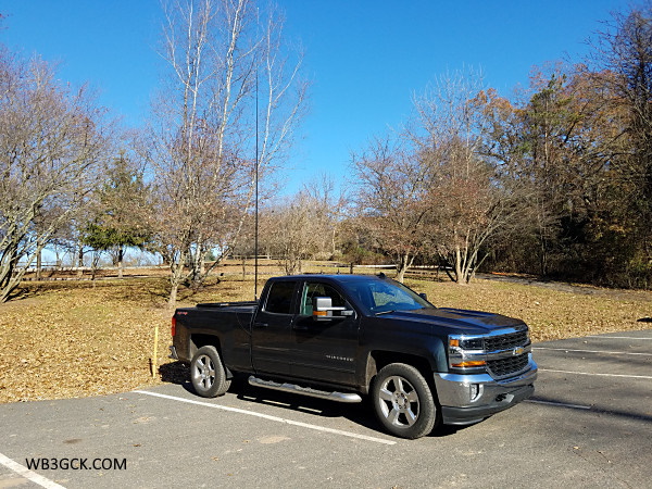
For today’s PBMME, I drove out to Upper Schuylkill Valley Park near Royersford, PA, one of my favorite portable locations. I was tempted to set up at a picnic table but, with the 39°F temperature (and a windchill of 29°F), I opted to operate from my truck. I went with my usual set up: my homebrew 19-foot vertical mounted on the truck and my KX3 up in the cab.
My operating location in Upper Schuylkill Valley Park for the November 2019 Polar Bear Moonlight Madness Event (PBMME).
I started on 40M and almost immediately got a call from VA2NB. Mike was operating from his cottage in Quebec. This was the first Polar Bear QSO for each of us in a long time. Unfortunately, Mike would be the only Polar Bear in my log today.
After working Mike, I went on to make another half-dozen QSOs, including a couple of two-way QRP contacts and some nice rag chews. I also picked up a new SKCC number from NC7H Idaho. There were a few other Polar Bears on the air but, sadly, I never heard them.
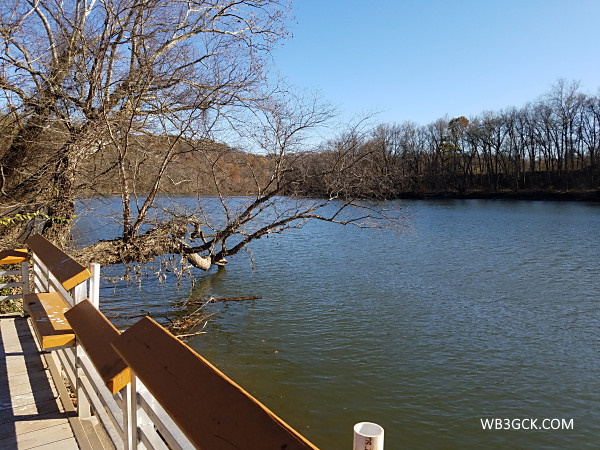
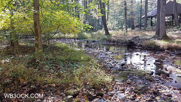
The Schuylkill River at Upper Schuylkill Valley Park
I was only out for 2 hours but it was a fun time. Thanks to VA2NB for preventing me from getting skunked today. I’m hoping that activity in the Polar Bear QRP Club will continue to grow.
Years back, I regularly ran QRPp. It’s been a while, so I had some fun getting re-acquainted with QRPp during this month’s SKCC Weekend Sprintathon (WES).
On Saturday, I headed out to Black Rock Sanctuary, one of my favorite spots for a quick stationary-mobile outing. The temperature was in the 30s, so I operated from my truck. I mounted my trusty 19-foot vertical on the back of the truck and set up the KX3 in the cab. I turned the power down to 1 watt and got busy looking for WES stations.
My set up at Black Rock Sanctuary during the November WES
The 40M band seemed to be in good shape, but there were RTTY stations all over the place. Despite the RTTY interference, I didn’t seem to have much difficulty making contacts. I didn’t have as much luck on 20M, but I did pick up two stations (Florida and Georgia).
After an hour and a half, I had to pack up to run some errands. I ended up with 8 contacts in the log. That’s better than I expected.
I didn’t have much time for radio this weekend, but I did pick up a couple more contacts from home on Sunday. It was a bit more of a challenge at home with my rainspout antenna. My final tally was 10.
It never ceases to amaze me what you can do with 1 watt. Thanks the great operators who managed to pull me out of the noise.
Last night was the annual Zombie Shuffle, one of my favorite QRP contests. The QRP zombies weren’t too scary, but the band conditions were frightful.
For the past two years, the Zombie Shuffle coincided with our last camping trip of the year. Since I put my little trailer into hibernation after last week’s trip, I had to operate from home using my meager rainspout antenna.
I tried 20M during daylight hours, but I never heard a single zombie there. The Reverse Beacon Network (RBN) showed I was getting out but not very well. I bagged 4 zombies on 40M, but that was a struggle at times. My noise level was high, signals were weak, and there was a lot of fading. One of those zombies was VE3MGY who was one of the bonus stations with this year’s Titanic theme—MGY was the Titanic’s callsign. I also ran into fellow Polar Bear QRPer, Mike VE3WMB.
Signals were a bit stronger on 80M and I picked up 5 zombies there. For some reason, my rainspout gets out well on that band. Towards the end, though, my KX3 had some issues keeping a match on 80M. I guess that means I need to do some maintenance on the rainspout antenna.
My QRP buddy, Ed WA3WSJ, used the Boschveldt QRP Club callsign (W3BQC) as an MGY bonus station. I was tracking him on RBN but I never heard him. However, I did work a another Boschveldt QRP friend, Glen NK1N. I also ran into an old QRP friend, KA3D. It was great to hear Dan again.
So, with a total of 9 zombies, I didn’t have my best year, but it sure wasn’t my worst. I was only 2 off from last year’s effort in the QRP camper.
Many thanks to Paul NA5N and Jan NØQT for another fun contest.
This is always a bittersweet time of year for me. While I enjoy camping in Fall, I also know that the camping season is drawing to a close. This past weekend was the final trip of the year for the QRP Camper.
My (far) better half and I took our little trailer to nearby French Creek State Park in Elverson, Pennsylvania. We usually start and end the season there. It’s close to home and it’s one of our favorite campgrounds.
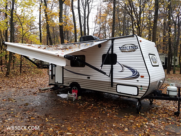
The WB3GCK “QRP Camper” as we were wrapping up our last camping trip of the year. We had the unpleasant task of packing up in a steady downpour.
My radio time was limited this weekend. We had our four grandchildren visit the campsite on Saturday. Most of Saturday was spent carving pumpkins with the kids and roasting hotdogs and marshmallows over the campfire.
I did manage to find time to make a half-dozen contacts, though. A couple of them were real nice rag chews. One of note was with K1LKP in New Hampshire. Carmen noted that our last QSO was 15 years ago while I was camping in Maryland. It sure was nice to work him again.
Looking back over the past camping season, I made a few small changes in how I operate from the camper. I mentioned in previous posts, that the 120VAC-to-12VDC converter in the trailer generates a huge amount of RF noise. I’ve been getting around that by killing the AC power to camper when I’m on the radio. All of the essential functions in the trailer (lights, refrigerator, water pump, water heater) automatically switch to battery or propane. In the chillier weather—like this weekend—, I run a separate extension cord into the trailer to power a small electric heater.
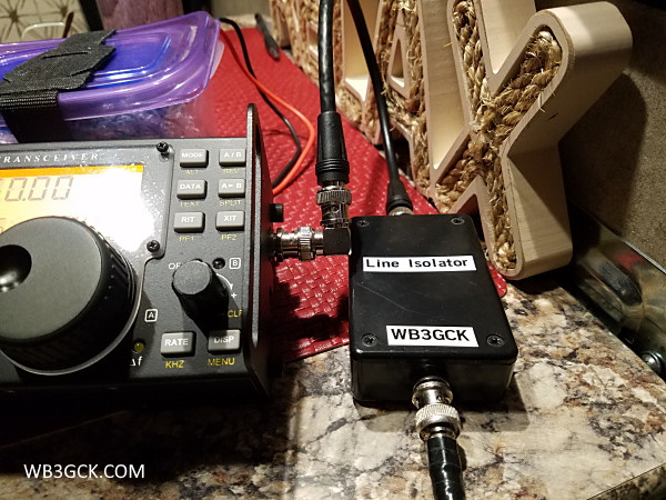
I also did some experimenting with the way I feed my antenna. My 29.5-foot vertical is fed through 9:1 unun and uses the coax shield as a counterpoise. I have never had any serious problems with RF in the shack, but I have noticed some minor fluctuations in SWR. I placed a common mode choke at the rig end, and that has made tuning more consistent. I built the common mode choke—or line isolator—a while back for other experiments. It’s now a permanent part of my set up in the camper.
This is the hombrew common mode choke that I have been using with my 29.5-foot vertical and 9:1 unun.
So, that wraps up another fun camping season with the QRP Camper. It’s now time to Winterize it and put it in storage until Spring. It’s not the end of my portable operating though; there’s still lots of outdoor radio fun to be had.
Our camping season is rapidly drawing to a close. My (far) better half and I took our little camper out to Colonel Denning State Park (POTA K-1343, WWFF KFF-1343) for our next-to-the-last trip of the year.
Located in central Pennsylvania, Colonel Denning was a new park for us. Our campsite for the weekend small but more than adequate. This section of the campground was along a creek and in a valley. There were steep hills directly behind our site. Given the terrain, I didn’t have high hopes for my radio waves getting out.
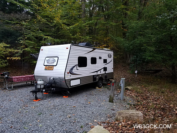
The WB3GCK “QRP Camper” at Colonel Denning State Park. My antenna is that white object to the rear of the camper.
We arrived on Friday afternoon. After getting the camper situated, I set up my antenna and gave the radio a quick test. Tuning around, I could hear some strong signals. That gave me some hope.
I didn’t get on the air until Saturday morning. It was only 35F overnight, so I hunkered down in the camper to operate. I made a few contacts, so I appeared to be getting out OK. On 40M, I worked WB9WIU in Indiana, some New York QSO Party stations, and had a 2-way QRP QSO with WA1LFD in New Hampshire.
Doubling Gap Creek in Colonel Denning State Park near our campsite.
Later in the day, I spotted myself on the POTA and WWFF websites and spent an hour or so working park chasers. I worked a lot of regulars including W6LEN in California. I had park-to-park QSOs on two bands (20M and 17M) with N4CD in Texas. At one point, I received a call from EA2IF in Spain, who mistakenly thought I was a SOTA activator. In any event, I was happy to add him to my log. I ended my brief POTA/WWFF session with 23 stations in the log.
We awoke Sunday morning to a steady rain. According to the local forecast, the day was going to be a washout—they were right. I made one final contact with K9FW on 80M before tearing down and packing up for the trip home.
The bands were in good shape over the weekend. Despite the terrain, my QRP signals seemed to have found their way out of the valley. Colonel Denning is on our list for a return visit next year.
Once a day, I receive an email from eBay showing the latest listings for CW keys. In one of those emails, a small and inexpensive set of 3D-printed paddles caught grabbed my attention. My curiosity got the better of me, and I ordered some.
The primary reason for my interest was the size. I normally use Palm Mini paddles attached to a clipboard, when I’m out operating portable. The eBay listing offered paddles that were a bit smaller than my Palm Mini paddles. The Palm paddles are no longer available (much to my chagrin), so I was curious if these cheap paddles might be a viable alternative. Given the low price (around $15, shipping included), I had no delusions that the no-name paddles would be as good, though.
They are available in 3 sizes. The two larger paddles have magnetic bases. I bought the smallest one (3x8x2 cm), which had the potential to work with my clipboard setup. They are intended for two-handed operation but I figured I could improvise some sort of magnetic base for them.
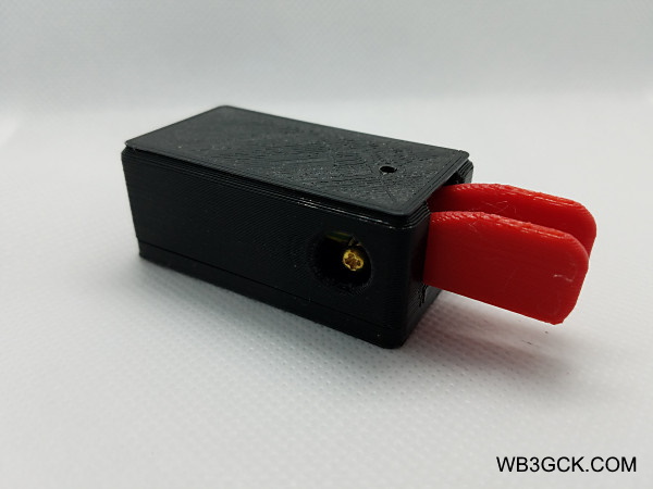
Unbranded, 3D-printed paddles from eBay. The screw (one on each side) adjusts the paddle contact spacing.
As mentioned earlier, they are 3D-printed. The seller cautions: “Can’t work in high temperature environment!” The term, “high temperature,” is undefined. I’m sure I would start to wilt in the heat long before the paddles.
It took a couple of weeks to receive my paddles from Hong Kong. Besides the paddles, the package contained a 3-foot patch cable with 3.5mm stereo plugs. There was no documentation but none was needed.
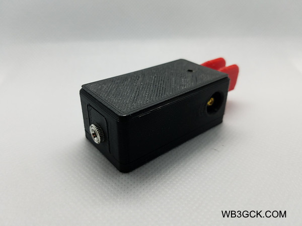
Read view of the small, un-branded, 3D-printed paddles from eBay. The rear connector is a standard 1/8-inch stereo jack.
Out of the box, I found the contact spacing to be much wider than I’m accustomed to. Fortunately, the paddles have access holes on each side to adjust the spacing. A few tweaks with a Phillips screwdriver got the spacing closer to my liking.
It was easy to fashion a magnetic base. Using some two-sided foam mounting tape, I added two strong magnets to the bottom of the paddles. The magnets didn’t line up exactly with the washers on my clipboard but they held pretty well.
You’re probably wondering how they work. Well, they are about what you’d expect from $15 paddles. For sure, they lack the solid, precise feel of my more expensive Palm paddles. The paddle arms have what I call, “vertical slop.” By that I mean you can wiggle them up and down. Also, the paddles’ contacts aren’t the greatest. They are just the threaded ends of two machine screws contacting the threads of a vertically-mounted machine screw.
With the “vertical slop” and the rough contacts, you don’t always get clean contact closure. To me, it feels like the contacts sometimes “scratch” when they close. The left paddle also sticks occasionally. At higher speeds (20+WPM), they can be challenging. That said, I am able to coax decent-sounding code out of them at moderate speeds—if I’m careful.
As they say, you get what you pay for. These paddles won’t be replacing my Palm Mini paddles anytime soon. They don’t have the smooth, quality feel of my Palm paddles—or any other paddles I own. Not by a long shot. I concede, however, that comparing these $15 paddles to more expensive products is not entirely fair.
CW keys and paddles are always subject to personal preferences; however, if you are on a limited budget, these paddles might work for you. It certainly won’t cost you a lot to find out.
73, Craig WB3GCK
[Disclaimer: I have no financial interest in these products whatsoever.]
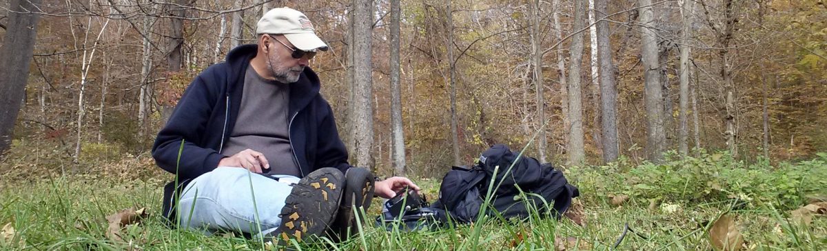
I think it’s a given: When you’re out in a public place with a radio and a 20-foot antenna pole, you’re bound to attract attention. In 26 years of portable operating, I’ve gotten more than my share of curious looks from passersby. At first, I was a little self-conscious, but now I don’t mind people wondering what this crazy old guy is up to.
For the most part, people will give my outdoor radio set-up a puzzled look and move on. Once in a while, a courageous spectator will approach me and ask what I’m doing.
There have been times when it’s a law enforcement officer who stops by. One park ranger in Delaware said she was responding to a call about “suspicious activity.” My antenna once attracted a police officer in Havre de Grace, Maryland. We wound up chatting for a bit, and he wished me luck as he drove off.
Recently, at a local park, a fisherman yelled over to me, “Hey, ham radio guy! How are they biting?” I’m guessing we had talked at some point in the past. I replied, “Pretty good. How are they biting for you?”
One of my favorite encounters happened during last year’s Skeeter Hunt contest. A fellow who walked up to ask about my antenna turned out to be one of my earliest childhood friends. We hadn’t seen each other in decades, so I’m glad his curiosity got the better of him.
Whatever the circumstances, I found it useful to give a 30-second elevator speech about ham radio. In business, an elevator speech is a short, easy to understand pitch—one that can be delivered during a short elevator ride. I keep it simple and non-technical. Often, if it suffices to tell them: “It’s ham radio.”
I try to be mindful of my environment. If I’m out in the woods by myself somewhere, my equipment is not likely to get in the way of other people. When I’m in a public place, however, I follow a few basic principles:
Stay Legal. Make sure you’re following all applicable rules for your location and, by all means, don’t trespass. If approached by authorities, be courteous and launch into your ham radio elevator speech.
Stay Self-Contained. When I’m in a public place, I like to keep my equipment set-ups as compact as I can. Some parks have issues with putting wires in trees, so I’ll go with a self-supported antenna, like a vertical or small loop. That’s OK; it’s less time I have to spend cursing at trees when my throws miss the mark.
Don’t Become a Hazard to Others. This goes hand-in-hand with staying self-contained. I like to make sure my equipment isn’t a hazard to other people in the area, so I try to find a location away from others. I also make sure coax or counterpoise wires aren’t a trip hazard and that there’s no risk of my antenna falling on anyone.
Leave No Trace – Make sure you leave the place as good as, if not better than, you found it. This is a good practice regardless of your location.
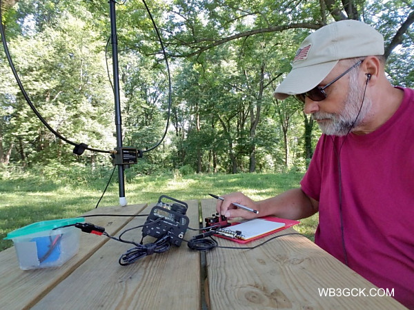
WB3GCK operating in Valley Forge National Historical Park. I was in a popular picnic area, so I chose a location away from other people. I also opted for a set-up that was confined to the picnic table I was using.
Some encounters with the public have resulted in interesting discussions. Here’s a small sampling of questions and comments I’ve heard over the years:
“Is that a fishing pole? Catch anything?”
“How far can you get out with that thing?”
“Is ham radio still a thing?”
“Cool! My uncle (or some other relative) used to be into ham radio.”
“Are you communicating with the Mother Ship?” (I have also heard Martians and other extraterrestrial references)
“Can you talk to truckers with that?”
“Morse Code? Is that still around?”
“How many channels can you pick up with that thing?” (Assuming, my antenna is for TV, I suppose.)
“What exactly are you broadcasting?”
So, when you’re out and about, don’t be afraid of the attention you might be drawing; welcome it. You never know; you might be inspiring a future ham.
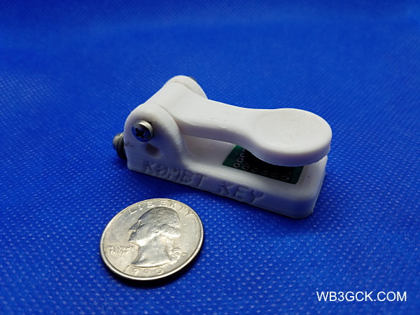
OK, I admit it. I have a fascination with tiny straight keys and paddles. With the proliferation of 3D printers, there are a lot of neat, innovative products available these days. This unusual little key from Dave Balfour KØMBT is a good example. [Update 3/16/2020: Dave recently changed his callsign to ADØB.]
Dave got started in 3D printing as a hobby a few years ago. A while back, he started sharing his straight key designs with his fellow SKCC members on the SKCC mailing list. That generated some interest and, before long, Dave was offering his keys for sale. As of this writing, Dave is offering straight keys in two sizes and a single lever paddle that can be used as a sideswiper (aka cootie) key.
I ordered the smaller of Dave’s straight keys, which he calls the “Mini-Mini.” Dave promptly shipped one and I had it a few days later. When I opened the box, I was immediately intrigued by this little key.
K0MBT “Mini-Mini” Key
When I say “little,” I mean “little.” Overall, it measures approximately 2-1/4″ L x 1″ W x 3/4″ H and weighs in at a minuscule 0.7 oz. (19g). Instead of a traditional knob, Dave uses a novel indentation on the keying lever. The other unique thing is the switch he uses instead of the contacts. A little computer mouse switch provides both the contact closure as well as the return spring. As a result, there are no adjustments for contact spacing or tension. It doesn’t get much simpler than this.
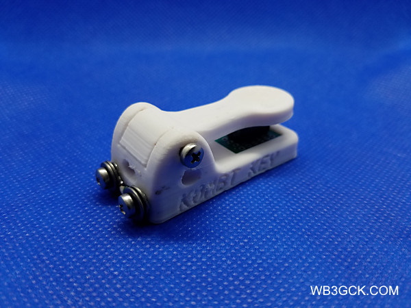
On the rear of the key, there are two terminals for connecting the wires of your choice. There are holes on each side of the key, that meet at the two terminals. You can route your wires in from the side, providing a little strain relief.
Rear view of the K0MBT “Mini-Mini” key
When I first grasped the key, my forefinger instinctively went into the indentation and it felt very natural. Despite the lack of adjustments, the key has a nice feel to it. With it just sitting on my desk, I can send code without the key sliding around too much. With the cable I’m using, though, it can sometimes feel like “the tail wagging the dog.” It’s not a huge issue, as long as I’m careful.
Kudos to Dave KØMBT for this unique and fun little key. If you’d like more information on Dave’s keys, look him up on QRZ.com or download Dave’s PDF file describing his offerings.
73, Craig WB3GCK
[Disclaimer: I have no financial interest in this product whatsoever.]
My (far) better half and I hitched up the “QRP camper” and headed north to the Pocono Mountains of Pennsylvania. Our destination for the weekend was Frances Slocum State Park. It was our first visit there and we had a great time. As a bonus, our trip coincided with the monthly SKCC Weekend Sprintathon (WES) contest.
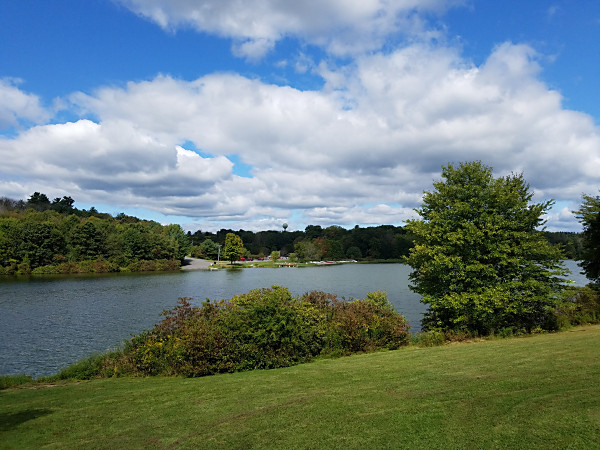
Frances Slocum State Park, located north of Wilkes-Barre, covers 1,035 acres. The centerpiece of the park is Frances Slocum Lake. The campground is relatively small and very quiet. Ours was one of the larger sites available and was nicely secluded.
Frances Slocum Lake
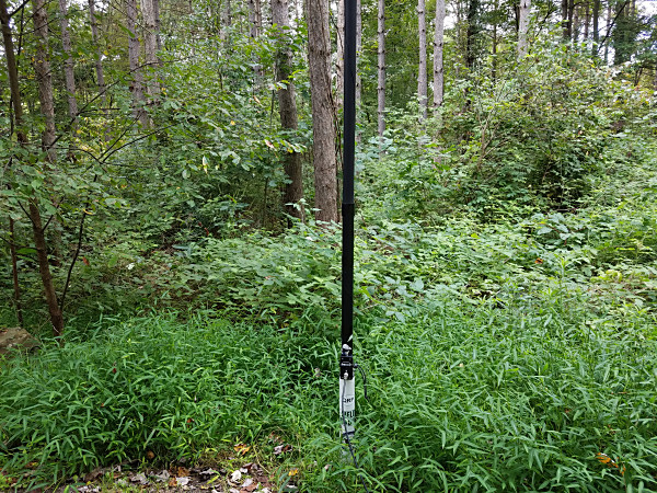
After getting the camper situated, I went about setting up my antenna. I had a bit of trouble driving in my Jackite pole ground mount. The ground was very rocky and it took 5 or 6 tries to find a spot to drive it in. I wound up putting it at the edge of our site near a large stand of pine trees.
My antenna at Frances Slocum State Park. It took 5 or 6 tries to find soft ground to drive in the ground mount.
I got on the air Saturday morning just as the WES contest was starting. In general, it seemed like my 5-watt signal was getting into the southern states with good signal reports but reaching New England was a problem at times. I’m guessing that the mountainous terrain surrounding the park was a factor.
WB3GCK doing some early morning operating inside the camper at Frances Slocum State Park
After operating on and off on Saturday (and a little bit early Sunday morning), I ended up with 20 WES contacts in 12 SPCs. Not too bad, considering the time I spent on the air. I also worked KX0R out in Colorado. This was the second camping trip in a row where I worked George during one of his SOTA activations.
All in all, it was a very nice weekend. The weather was great and the radio wasn’t too bad.